
Mouse with touch area

A technology of touch area and mouse, which is applied in the input/output process of data processing, input/output of user/computer interaction, instruments, etc., and can solve problems such as difficulty in realizing midpoint positioning in three-dimensional space, heavy workload, and unreasonableness , to achieve the effect of reducing learning and adaptation costs

Active Publication Date: 2022-04-29
SOUTH CHINA UNIV OF TECH
View PDF4 Cites 0 Cited by
  • Summary
  • Abstract
  • Description
  • Claims
  • Application Information

AI Technical Summary

Problems solved by technology

[0015] The current mouse forms a three-dimensional space through the two-dimensional combination of different orientation views, such as CAD, sketchup, etc., are all two-dimensional working planes, which can only realize the two-dimensional positioning of the cursor on the current screen, and it is difficult to realize the midpoint of the three-dimensional space. position
When operating on a three-dimensional structure, it is necessary to spatially locate and operate related elements. The traditional mouse can only provide two dimensions, but in the scene of extended reality technology (VR, AR and MR), it is necessary to provide a third dimension to solve the problem of space. Moreover, the current application of extended reality technology often even relies on the handle, and the use of the handle requires the user to move the handle in space during the entire operation process, and sometimes even requires the user to move in space or physically Performing body movements, which is obviously unreasonable for jobs with a large workload or long working hours, and few people are currently developing other products

Method used


Image

  • Mouse with touch area
  • Mouse with touch area
  • Mouse with touch area

Examples


Embodiment 1

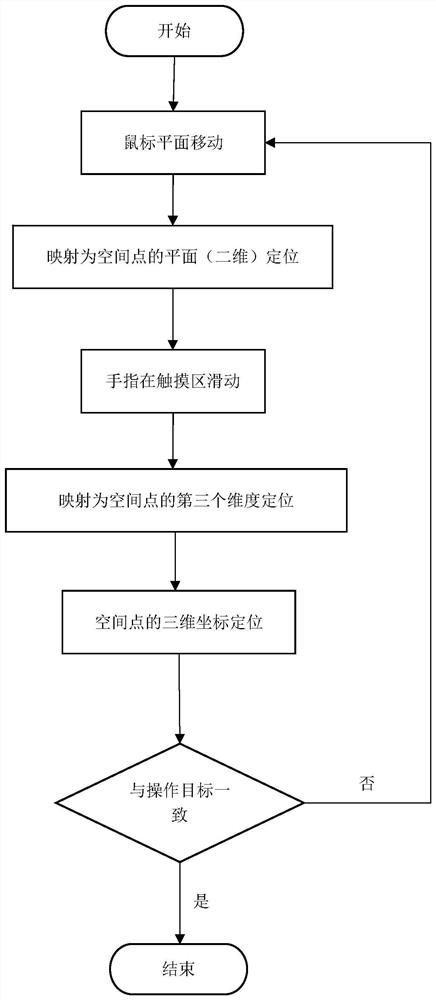
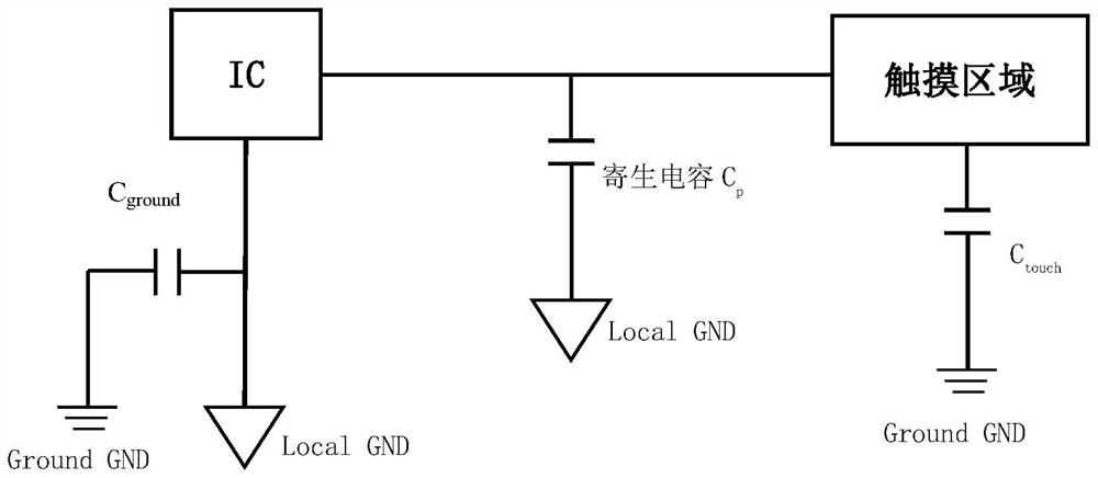
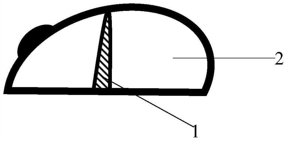
[0039] Such as image 3 , Figure 4 A mouse with a touch area in this embodiment includes a touch panel 1 (thumb sliding touch area), a touch panel sensor, and the touch panel sensor is a finger track conductive circuit printed on the surface of the touch panel. The touchpad 1 detects the amount of capacitance change, and converts the detected capacitance change into the coordinates of the third dimension; the touchpad sensor is located in the finger track conduction area on the surface of the touchpad, and the plane movement of the mouse positions the cursor on the screen On the two-dimensional plane, when the finger slides on the touchpad 1, the displacement in the third dimension is realized, so as to realize the three-dimensional positioning of the point. The three-dimensional positioning means that when the mouse plane moves, displacement in the horizontal and vertical directions or displacement in the third direction generates a set of dynamic coordinates that change wi...

Embodiment 2

[0046] The method of converting to the third dimension can also add a dimension on the basis of the two-dimensional positioning of the original cursor. The finger moves on the touchpad to control the zoom in or out of the three-dimensional object, or to control the positioning and directional movement of the three-dimensional object .

[0047] When the mouse moves, the displacement of the cursor in the horizontal and vertical directions can be calculated, and then a set of dynamic coordinates that change with the mouse movement can be generated. This dynamic coordinate determines the position and movement of the mouse on the screen, allowing the user to position the cursor on the screen plane to generate a two-dimensional coordinate. The displacement in three directions, that is, the third dimension generates coordinates, which can be combined to realize the spatial positioning of points and generate a three-dimensional coordinate.

[0048] Such as Figure 5 As shown, assume...

Embodiment 3

[0052] Such as Figure 6 As shown, when the global coordinate system of the working scene is a cylindrical coordinate system, set θ=θ 0 Represents a half-plane passing through the z-axis, r=r 0 Represents a cylindrical surface with z as the axis; assign different values ​​to r when the finger slides in the mouse touch area, and there will be cylinders with different distances in the virtual scene; when the finger leaves the mouse touch area, r=r 1 The cylinder is a two-dimensional surface. The working plane of the user using the mouse is mapped to the two-dimensional surface in the work scene. The mouse moves on the plane of the work desktop and is mapped to a point on the cylinder in the extended display scene space. The two-dimensional coordinates (θ, z) of the three-dimensional coordinates (r 1 , θ, z).


PUM


Abstract

The invention discloses a mouse with a touch area, which comprises a touch pad and a touch pad sensor which are positioned on the side surface of the mouse, and is characterized in that the touch pad detects capacitance variation and converts the detected capacitance variation into coordinates of a third dimension; the touch pad sensor is located in a finger track conduction area on the surface of the touch pad, a cursor is positioned on a two-dimensional plane of a screen through plane movement of the mouse, and when a finger slides on the touch pad, positioning of a third dimension is generated, so that three-dimensional positioning of a point is achieved. According to the invention, the current use situation that the application of the current augmented reality technology depends on a handle is improved, a user does not need to move the handle spatially in the whole operation process, the user does not need to move spatially or carry out body actions on limbs, and the operation efficiency is greatly improved for the operation with large workload or long working time. In a working environment in which only functions are added by using original familiar equipment, the learning and adaptation cost is reduced.

Description

technical field [0001] The invention belongs to the technical field of auxiliary equipment for electronic products, in particular to a mouse with a touch area. Background technique [0002] The mouse is an input device of the computer. It is named for its shape like a mouse. It can locate the horizontal and vertical coordinates of the computer monitor. It can be divided into several types such as rolling ball mouse, optical mouse, and wireless mouse. Wherein the photoelectric mouse first detects the displacement signal of the mouse, and converts it into an electric pulse signal, and then controls the movement of the cursor on the computer monitor through a program. [0003] Compared with the rolling ball mouse, the photoelectric mouse replaces the traditional rolling ball with a photoelectric sensor, making its positioning more accurate and moving more smoothly. Compared with the wireless mouse, the optical mouse has one more wire than the wireless mouse, but its response i...

Claims


Application Information

Patent Timeline
Patent Type & Authority Applications(China)
IPC IPC(8): G06F3/0346G06F3/0354G06F3/01
CPCG06F3/0346G06F3/03547G06F3/011Y02D10/00
Inventor 魏鹏孙倩徐佳琦
Owner SOUTH CHINA UNIV OF TECH
Learn More