Driving circuit, driving chip and display device

A technology for driving circuits and displaying signals, which is applied in the fields of driving circuits, driving chips, and display devices. It can solve problems such as increasing power consumption, limiting display data accuracy, and affecting display effects, so as to reduce chip cost and power consumption, and eliminate cross-board Chromatic aberration, the effect of improving display accuracy

Active Publication Date: 2022-04-29
CHENGDU LIPPXIN MICROELECTRONIC CO LTD
View PDF14 Cites 2 Cited by
  • Summary
  • Abstract
  • Description
  • Claims
  • Application Information

AI Technical Summary

Problems solved by technology

In the prior art, LED is a column driver chip, and the accuracy of display data usually processed is limited. For example, it may only process display data expressed in integers. For example, the actual display data is 3.4T, while the column driver chip can only display data in Drive for 3T, which will inevitably lead to greatly reduced display effect
Especially in the case of low gray, the loss of 0.4T will seriously affect the display effect
At present, on the one hand, in order to improve the display accuracy, higher display accuracy is usually obtained at the cost of increased power consumption and chip cost; on the other hand, the low-gray compensation effect of the image in the prior art is not obvious, And the compensation method is complicated

Method used


Image

  • Driving circuit, driving chip and display device
  • Driving circuit, driving chip and display device
  • Driving circuit, driving chip and display device

Examples


Embodiment Construction

[0051] The technical solution of the present application will be further described below in conjunction with specific embodiments. It should be noted that the protection scope of the present application is not limited to the following description.

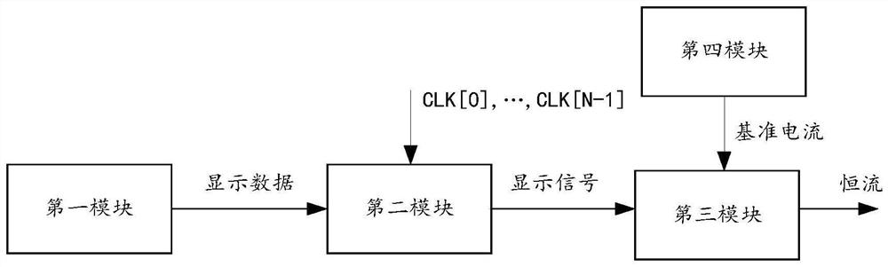
[0052] The present application provides a driving circuit such as figure 1 mentioned, which includes:

[0053] The first module generates display data based on image information;

[0054] The second module generates a display signal based on the display data and multiple clock signals;

[0055] The third module outputs a constant current based on the display signal;

[0056] Wherein, the difference between two adjacent clock signals among the plurality of clock signals is M complete clock periods, 0≤M<1.

[0057] The image data information transmitted from outside can be stored in the SRAM; the image information can be correlatively processed by the first module to generate display data and stored. This processing may include a...


PUM


Abstract

A driving circuit includes: a first module generating display data based on image information; the second module is used for generating a display signal based on the display data and a plurality of clock signals; the third module is used for outputting constant current based on the display signal; the fourth module is used for providing reference current for the third module; the fourth module comprises a reference voltage generation module, a bias module, a current generation module and a pre-charging module. The difference between two adjacent clock signals in the plurality of clock signals is M complete clock cycles, and M is more than or equal to 0 and less than 1. According to the circuit, high image display precision can be achieved with low system power consumption and low chip cost, and meanwhile effective image low-gray compensation is achieved.

Description

technical field [0001] The present application relates to the display field, in particular to a driving circuit, a driving chip, and a display device. Background technique [0002] A display device is usually driven by a row driver chip and a column driver chip to realize display. The column driver chip is usually a constant current driver chip. The output terminal of the constant current driver chip is connected to the column line of the LED. During the effective period of the display signal, that is, the PWM signal, a constant current is output to drive the LED lamp beads on the column line to emit light. . [0003] The display accuracy can be used to measure the quality of the LED display device. Generally, the higher the display accuracy is, the better the display quality will be when displaying images. In the prior art, LED is a column driver chip, and the accuracy of display data usually processed is limited. For example, it may only process display data expressed in...

Claims


Application Information

Patent Timeline
Patent Type & Authority Applications(China)
IPC IPC(8): G09G3/32
CPCG09G3/32G09G2320/0271Y02D10/00G09G3/20G09G2310/0275G09G2310/08G09G2310/0291G09G3/2011G09G2310/027G09G2330/021
Inventor 唐永生黄立芦世雄
Owner CHENGDU LIPPXIN MICROELECTRONIC CO LTD
Why Eureka
Try Eureka