Automatic assembling equipment for connector

An automatic assembly and connector technology, applied to the assembly/disassembly of contacts, etc., can solve the problems of low assembly efficiency and low yield

Pending Publication Date: 2022-04-29
WEIFANG LOKOMO PRECISION IND
View PDF0 Cites 0 Cited by
  • Summary
  • Abstract
  • Description
  • Claims
  • Application Information

AI Technical Summary

Problems solved by technology

[0003] The purpose of the present invention is to provide an automatic connector assembly equipment, aiming to solve the problems of low efficiency and low yield of existing assembly methods

Method used


Image

  • Automatic assembling equipment for connector
  • Automatic assembling equipment for connector
  • Automatic assembling equipment for connector

Examples


Embodiment Construction

[0032] In order to make the object, technical solution and advantages of the present invention clearer, the present invention will be further described in detail below in conjunction with the accompanying drawings and embodiments. It should be understood that the specific embodiments described here are only used to explain the present invention, not to limit the present invention.

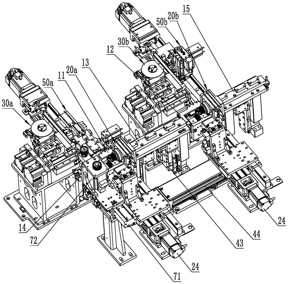
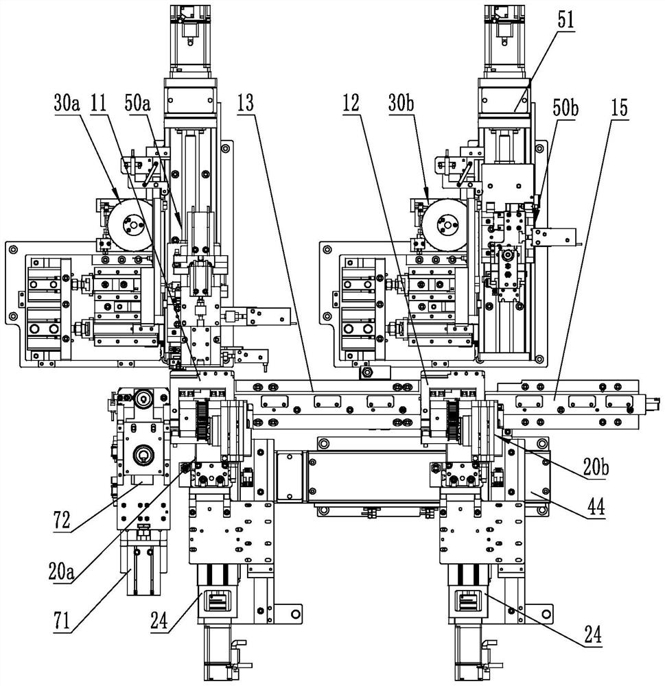
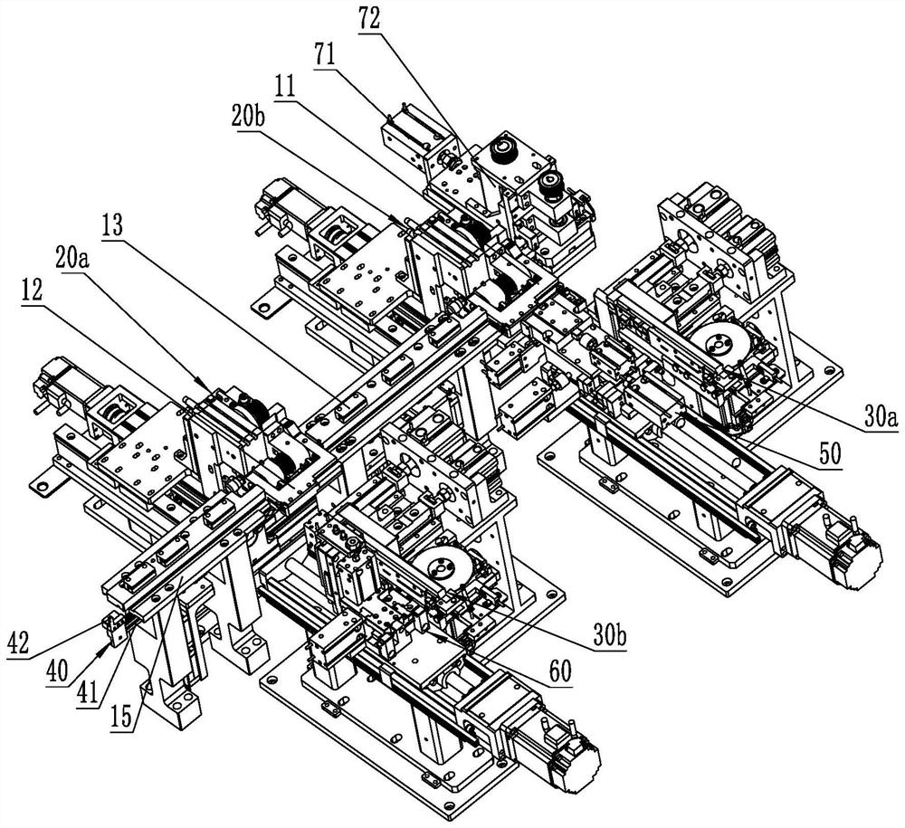
[0033] Figure 1 to Figure 14 is a schematic structural view of the connector automatic assembly equipment of the embodiment of the present invention, wherein, figure 1 It shows a three-dimensional structural schematic view (1) of the automatic connector assembly equipment of the embodiment of the present invention, figure 2 It shows a schematic top view structural diagram of the connector automatic assembly equipment according to the embodiment of the present invention, image 3 A schematic diagram (2) showing the three-dimensional structure of the automatic connector assembly equipment of the ...


PUM


Abstract

The invention belongs to the technical field of connector assembling, and particularly relates to automatic connector assembling equipment which comprises two sections of overturning material channels and a middle material channel connected between the two overturning material channels. One side of the conveying channel is provided with an overturning driving device for driving the overturning material channels to rotate along the axis parallel to the conveying channel, the other side of the conveying channel is provided with feeding devices corresponding to the positions of the two overturning material channels, and the side portion of each feeding device is provided with a loading device; the two loading devices are respectively arranged corresponding to two adjacent end parts or two far-away end parts of the two overturning material channels, the shifting fork structure is arranged corresponding to the conveying channel, the shifting fork translation driving mechanism and the shifting fork lifting driving mechanism are arranged corresponding to the shifting fork structure, and the two overturning material channels and the middle material channel are respectively provided with seams for the shifting fork structure to insert; the problems that an existing assembling mode is low in efficiency and low in yield are solved.

Description

technical field [0001] The invention belongs to the technical field of connector assembly, in particular to an automatic connector assembly equipment. Background technique [0002] Fixing mounting brackets at both ends of the plastic case of the connector has become a common design in the industry. At present, the brackets are mainly assembled by semi-automatic equipment or manually. Not only is the efficiency relatively low, but the yield rate cannot be guaranteed. Contents of the invention [0003] The purpose of the present invention is to provide an automatic connector assembly equipment, aiming to solve the problems of low efficiency and low yield of existing assembly methods. [0004] The invention discloses an automatic assembly device for a connector. The automatic assembly device for a connector includes two sections of overturning material channels arranged at intervals, an intermediate material channel connected between the two overturning material channels, and...

Claims


Application Information

Patent Timeline
Patent Type & Authority Applications(China)
IPC IPC(8): H01R43/20
CPCH01R43/20
Inventor 李培欣韩海庆赵军栋杜建华
Owner WEIFANG LOKOMO PRECISION IND
Why Eureka
Try Eureka