Supercharge Your Innovation With Domain-Expert AI Agents!

Unilateral axial magnetic adjusting device of vertical hybrid excitation motor

A hybrid excitation motor, unilateral technology, applied in the direction of electromechanical devices, electrical components, electric components, etc., to achieve the effect of reducing heat, reducing complexity and improving service life

Pending Publication Date: 2022-04-29
ZHENGZHOU UNIVERSITY OF LIGHT INDUSTRY
View PDF0 Cites 0 Cited by
  • Summary
  • Abstract
  • Description
  • Claims
  • Application Information

AI Technical Summary

Problems solved by technology

[0003] The technical problem to be solved by the present invention is: aiming at the technical problem that in the existing axial-radial hybrid excitation motor, different excitation winding currents need to be manually switched externally to change the axial magnetomotive force, and then adjust the magnetic field strength of the main air gap of the motor. The invention proposes a unilateral axial magnetic adjustment device for a vertical hybrid excitation motor, which uses the different axial wind forces generated by the inner and outer claw poles of the motor at different speeds, moves the adjustment rod, and switches the number of turns of the excitation winding to change the axial magnetomotive force , and then adjust the magnetic field strength of the main air gap of the motor to realize the adaptive magnetic regulation of the hybrid excitation motor

Method used


Image

  • Unilateral axial magnetic adjusting device of vertical hybrid excitation motor
  • Unilateral axial magnetic adjusting device of vertical hybrid excitation motor
  • Unilateral axial magnetic adjusting device of vertical hybrid excitation motor

Examples


Embodiment 1

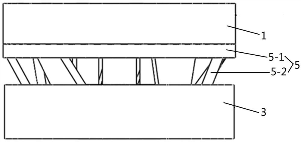
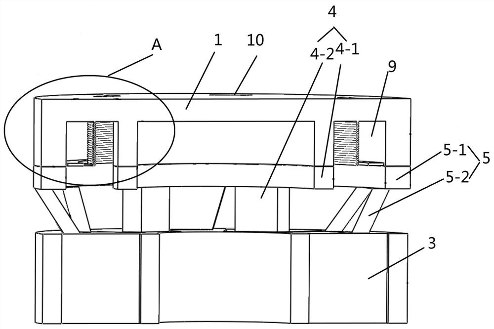
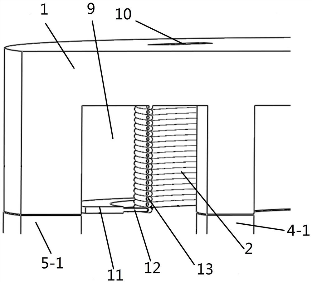
[0040] Embodiment 1: The tangential permanent magnet motor forms the magnetic N area 7 and the magnetic S area 8 distributed at intervals on the rotor 3, and the inner claw pole yoke part 4-2 is placed in the magnetic N area 7, and the outer claw pole yoke part 5 -2 is placed in the magnetic S area 8, the inner claw pole 4 and the outer claw pole 5 rotate with the motor rotor 3; the main magnetic circuit of the permanent magnet 6 in the tangential permanent magnet motor is the permanent magnet 6N pole -> rotor 3 -> Stator->rotor 3->permanent magnet 6S pole; because the inner claw pole 4 and the outer claw pole 5 are made of materials with high magnetic permeability, the permanent magnet 6 will pass through the inner claw pole 4, the outer claw pole 5 and the terminal Cover 1 forms an axial flux leakage, which is not available in the original permanent magnet motor. The axial flux leakage magnetic circuit is permanent magnet N pole -> rotor magnetic N area 7 -> inner claw pole 4...

Embodiment 2

[0059] Embodiment 2: Different from Embodiment 1, the outside of the outer claw pole ring 5-1 is a regular ring-shaped structure, and the inside is a pentagonal structure, which can make the outer claw pole 5 more magnetically conductive, and the The structure can give full play to the upward wind generated by the outer claw pole yoke part 5-2.


PUM


Abstract

The unilateral axial magnetic adjusting device comprises an end cover, an excitation winding, claw poles and a rotor, the claw poles are arranged between the end cover and the rotor, the claw poles comprise an inner claw pole and an outer claw pole, an annular groove is formed in the end cover, and ventilation holes are evenly distributed in the positions, located at the annular groove, of the upper end face of the end cover. An exciting winding and a moving piece are arranged in the annular groove, one end of the moving piece is in contact connection with the outer wall in the annular groove, the other end of the moving piece is in contact connection with the exciting winding through an adjusting rod, the exciting winding is arranged on the inner wall side in the annular groove, the adjusting rod is conductive and connected with a winding outgoing line, and the moving piece is non-conductive and can move up and down; and the annular groove is arranged above a gap between the inner claw pole and the outer claw pole. The outer claw pole rotates to generate upward wind to blow the moving piece and the adjusting rod to move, so that the number of turns of the winding is automatically switched, the change of axial magnetic flux is realized, and a radial main air gap magnetic field is adaptively adjusted.

Description

technical field [0001] The invention relates to the field of hybrid excitation motors, in particular to a unilateral axial magnetic adjustment device for a vertical hybrid excitation motor. Background technique [0002] Due to its advantages of high efficiency and high power density, permanent magnet motors have become the mainstream type of motors used in electric vehicles, and their share shows an increasing trend year by year. It is difficult to adjust the air-gap magnetic field of traditional permanent magnet synchronous motors, which leads to a narrow constant power area and a limited operating speed range; the existing axial-radial hybrid excitation motors add excitation windings in the axial direction of the motor, and by adjusting the current of the excitation windings The size of the motor is used to adjust the magnetic field of the main air gap of the motor, but the adjustment of the current size requires manual switching to be realized, and the operation is compli...

Claims


Application Information

Patent Timeline
Patent Type & Authority Applications(China)
IPC IPC(8): H02K3/20H02K3/24H02K3/50H02K5/20
CPCH02K3/20H02K3/24H02K3/50H02K5/207H02K2201/03H02K2213/03H02K2201/12
Inventor 邱洪波张钰清伊然何坤梁广川马晓璐熊斌李伟力吴宣东俞志君王浩亮刘玉宝赵强
Owner ZHENGZHOU UNIVERSITY OF LIGHT INDUSTRY
Features
  • R&D
  • Intellectual Property
  • Life Sciences
  • Materials
  • Tech Scout
  • Unparalleled Data Quality
  • Higher Quality Content
  • 60% Fewer Hallucinations
Learn More