
Plane positioning device based on guiding magnetic scale and positioning method thereof

A positioning device and plane positioning technology, applied in the directions of ground navigation, program-controlled manipulator, manipulator, etc., can solve the problems of inconvenient use and expensive plane positioning equipment, and achieve the effect of low cost, fast automatic search and positioning

Pending Publication Date: 2022-05-03
SICHUAN WINDOM PHOTOELECTRIC TECH
View PDF6 Cites 0 Cited by
  • Summary
  • Abstract
  • Description
  • Claims
  • Application Information

AI Technical Summary

Problems solved by technology

[0005] The purpose of the present invention is: the present invention provides a plane positioning device and its positioning method based on the guide magnetic mark, which solves the problems of high cost and inconvenient use of the existing plane positioning equipment

Method used


Image

  • Plane positioning device based on guiding magnetic scale and positioning method thereof
  • Plane positioning device based on guiding magnetic scale and positioning method thereof

Examples


Embodiment 1

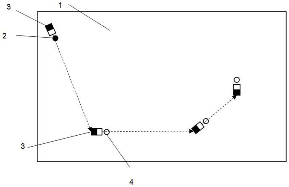
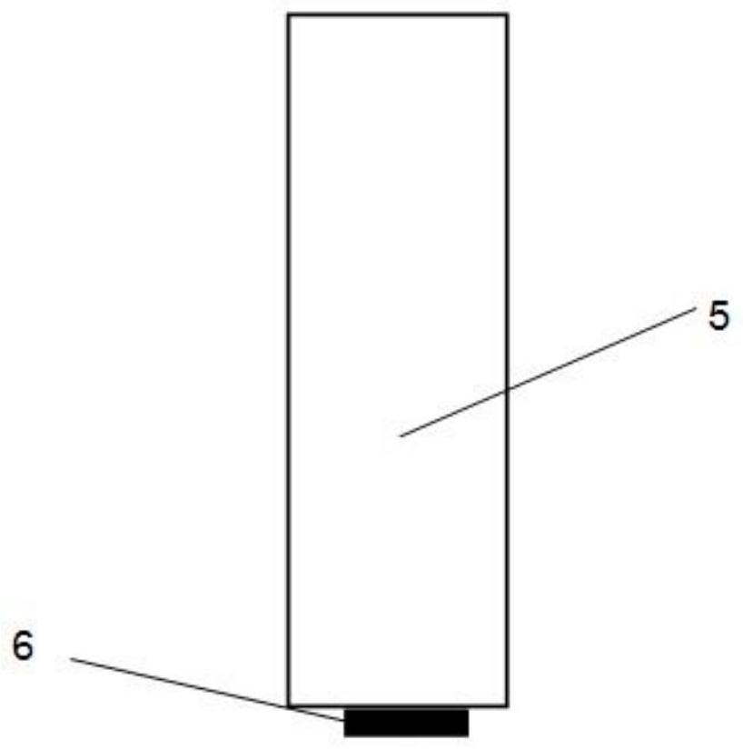
[0037] refer to figure 1 and figure 2 As shown, a plane positioning device based on a guiding magnetic mark includes a non-magnetic sample plate 1 and a mechanical arm 5 . The non-magnetic sample plate 1 is preferably a non-ferromagnetic sample plate. The non-magnetic sample plate 1 is provided with a start position 2 and a sample position 4. The position coordinates of the start position 2 on the non-magnetic sample plate 1 are known.

[0038] Both the starting position 2 and the sample position 4 are provided with a guide magnetic mark 3, the start position 2 and the sample position 4 are located at the magnetic poles of the guide magnetic mark 3, and the magnetic field direction of the previous guide magnetic mark 3 points to the next sample position 4. The magnetic field of the guiding magnetic mark 3 is used to magnetically guide the mechanical arm 5 to form a movement path of the mechanical arm 5 .

[0039] There is an included angle between the magnetic field directi...

Embodiment 2

[0046] refer to figure 1 and figure 2 As shown, a positioning method of the above-mentioned positioning device starts from the initial position 2, and each place is provided with a bar magnet or a coil, and the direction of its magnetic field points to the next sample position. Each sample position 4 is set at a certain fixed magnetic pole of the guiding magnetic mark 3 , that is, after accurately positioning the designated magnetic pole position of the guiding magnetic mark, the mechanical arm can then be aligned with the sample position.

[0047] The sample position is set at the N magnetic pole of each guiding magnetic mark, and the relative orientation from the N magnetic pole is fixed and known.

[0048] In this way, the robotic arm performs positioning and identification of each sample position according to the following steps:

[0049] a. The robotic arm 5 runs to the starting position 2 according to the known coordinates of the starting position 2.

[0050] b. The ...


PUM


Abstract

The invention discloses a plane positioning device based on a guiding magnetic scale and a positioning method thereof. The device comprises a non-magnetic sample plate and a mechanical arm, a starting position and sample positions are arranged on the non-magnetic sample plate, guiding magnetic marks are arranged between the starting position and the sample positions and between the sample positions, and a magnetic sensor is arranged on the mechanical arm. According to the positioning method, the mechanical arm induces the magnetic field direction of the guiding magnetic scale through the magnetic sensor, and guiding movement and sample position positioning are carried out. The method has the beneficial effects that the positioning of a plane article position is realized without an expensive servo system and a position, angle sensing and visual positioning identification system; the mechanical arm does not need to predict the coordinate point of each position in advance, and can quickly and automatically search and position; and the function of identifying the position'serial number 'is realized at extremely low cost.

Description

technical field [0001] The invention belongs to the technical field of equipment workpiece positioning, in particular to a plane positioning device and a positioning method based on a guide magnetic mark. Background technique [0002] In automatic production equipment and instruments, it is often necessary to place items on a plane mechanism for operations such as transfer and processing of items. After the movement, the moving items need to be positioned, identified, and grasped by the robotic arm. [0003] On the planar mechanism, each item has a unique number, and it is necessary to record which sample position each item is placed on the plate when loading the sample. After the operation movement, it is necessary to use the robotic arm to locate each sample position for grabbing, and grab the items in this position to the designated position, and the front and rear of the items cannot be out of order. [0004] In traditional technical solutions, the positioning of the f...

Claims


Application Information

Patent Timeline
Patent Type & Authority Applications(China)
IPC IPC(8): B25J19/02B25J9/10B25J9/16G01C21/08
CPCB25J19/027B25J9/10B25J9/16B25J9/1679G01C21/08
Inventor 王德麾姜世平董小春杨武谢伟民张宜文
Owner SICHUAN WINDOM PHOTOELECTRIC TECH
Features
  • Generate Ideas
  • Intellectual Property
  • Life Sciences
  • Materials
  • Tech Scout
  • Unparalleled Data Quality
  • Higher Quality Content
  • 60% Fewer Hallucinations
Learn More