Intelligent diving following robot, following system and following method
A robot-following, intelligent technology, applied in underwater operation equipment, transportation and packaging, ships, etc., can solve the problem that propellers are easy to hurt divers, and achieve the effect of improving reliability
- Summary
- Abstract
- Description
- Claims
- Application Information
AI Technical Summary
Problems solved by technology
Method used
Image
Examples
Embodiment 1
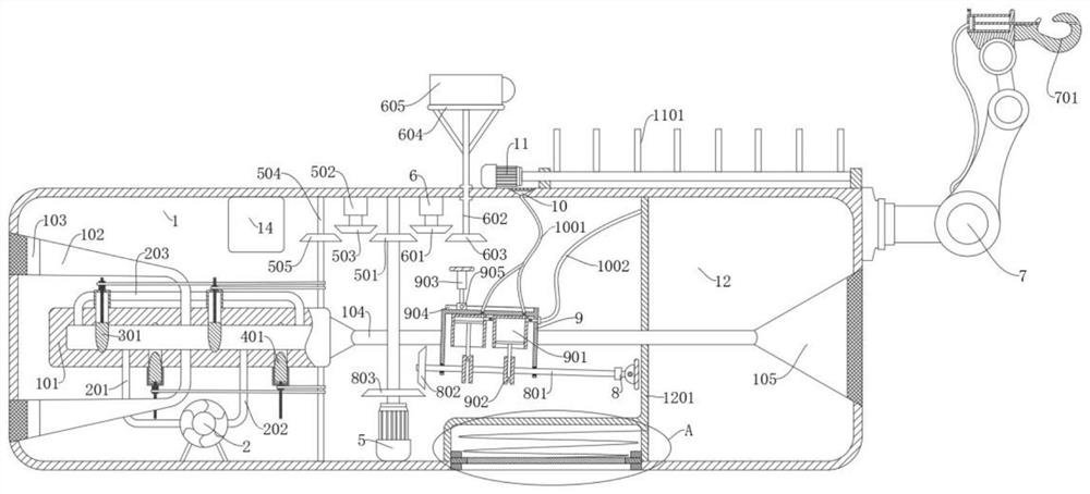
[0034] refer to Figure 1-6 , an intelligent diving following robot, including a housing 1, a first communication port 103 and a second communication port 105 located on the front and rear sides of the housing 1, a water pump 2 located in the housing 1, and also includes: for changing the first The communication port 103 and the flow control cylinder 101 in the direction of water flow in the second communication port 105, the first communication port 103 communicates with the flow control cylinder 101 through the first pipeline 102, and the second communication port 105 communicates with the flow control cylinder through the second pipeline 104 101 are connected, and the first communication port 103 and the second communication port 105 are provided with filter screens to prevent foreign matter from entering the water.
[0035] The water pump 2 is used to transport the water outside the casing 1 to the flow control cylinder 101 for internal discharge, and then drive the casing...
Embodiment 2
[0041] refer to Figure 1-6 , on the basis of Example 1, further,
[0042] It also includes a first hollow cover 3 and a second hollow cover 4 fixedly connected to the side wall of the flow control cylinder 101. connected.
[0043] The first cutoff block 301 is slidably connected in the first hollow cover 3 , and the first cutoff block 301 can move into the inner cavity of the flow control cylinder 101 to cut off the water flow.
[0044] The second cutoff block 401 is slidably connected in the second hollow cover 4 , and the second cutoff block 401 can move into the inner cavity of the flow control cylinder 101 to cut off the water flow.
[0045] A control mechanism is also provided in the casing 1, and the control mechanism can control the first shutoff block 301 or the second shutoff block 401 to make the inner cavity of the flow control cylinder 101 conduct or close.
[0046] When the first cutoff block 301 is located in the inner cavity of the flow control cylinder 101 ...
Embodiment 3
[0053] refer to Figure 1-6 , on the basis of Example 2, further,
[0054] This embodiment discloses a control mechanism. The control mechanism includes a first motor 5 located in the casing 1, a first rotating shaft 504 connected in the casing 1 in rotation; a first screw thread connected in the first hollow cover 3 in rotation. The sleeve 302 , the first threaded rod 303 fixed on the first cut-off block 301 , the first threaded rod 303 extends out of the first hollow cover 3 and is screwed to the first threaded sleeve 302 .
[0055] Rotate the second threaded sleeve 402 connected on the second hollow cover 4, the second threaded rod 403 fixed on the second shut-off block 401, the second threaded rod 403 extends out of the second hollow cover 4 and connects to the second threaded sleeve 402 threaded connection.
[0056] A first belt 304 is connected between the first threaded sleeve 302 and the first rotating shaft 504 , a second belt 404 is connected between the second thr...
PUM
 Abstract
Description
Claims
Application Information
 - R&D
- Intellectual Property
- Life Sciences
- Materials
- Tech Scout
- Unparalleled Data Quality
- Higher Quality Content
- 60% Fewer Hallucinations
Browse by: Latest US Patents, China's latest patents, Technical Efficacy Thesaurus, Application Domain, Technology Topic, Popular Technical Reports.
© 2025 PatSnap. All rights reserved.Legal|Privacy policy|Modern Slavery Act Transparency Statement|Sitemap|About US| Contact US: help@patsnap.com


