
Substrate frame rotation driving device for continuous coating production line

A coating production line, rotary drive technology, applied in the direction of sputtering coating, vacuum evaporation coating, ion implantation coating, etc., can solve the problems of increasing the number of nodes, increasing the length of the production line body, increasing the workshop space, etc.

Pending Publication Date: 2022-05-03
洛阳生波尔真空装备有限公司
View PDF0 Cites 0 Cited by
  • Summary
  • Abstract
  • Description
  • Claims
  • Application Information

AI Technical Summary

Problems solved by technology

When the product requires more coating layers, the coating processing process requires more, and the required target positions also need to increase accordingly, resulting in an increase in the number (quantity) of coating vacuum chambers required, and ultimately As a result, the length of the production line body increases, and the required workshop space also increases
However, due to the limitation of the length of some factories, it is impossible to place a continuous production line with a total length of too long, so it is impossible to prepare products with complex film requirements.

Method used


Image

  • Substrate frame rotation driving device for continuous coating production line
  • Substrate frame rotation driving device for continuous coating production line
  • Substrate frame rotation driving device for continuous coating production line

Examples


Embodiment Construction

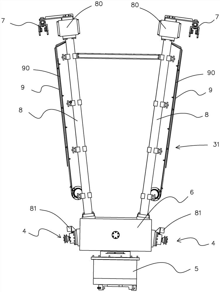
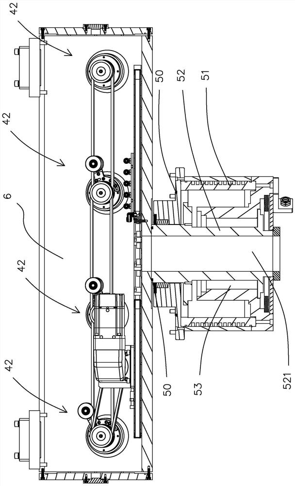
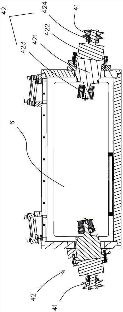
[0027] A substrate rack rotary drive device for a continuous coating production line, comprising a rotary frame 31, a transfer assembly 4 located on the side of the rotary frame 31 and used to drive the substrate frame body 10 into or out of the vacuum rotary chamber 1, and located on The bottom of the rotary frame 31 is used to drive the rotary drive member 5 to rotate the rotary frame 31 by 180°. The rotary drive member 5 includes a stator 51 fixed at the bottom of the vacuum rotary chamber 1 and a rotor 52 rotatably arranged in the stator 51. A seal 50 is provided between the stator 51 and the vacuum rotary chamber 1 , and a magnetic fluid sealing chamber 53 for filling magnetic fluid is provided between the rotor 52 and the stator 51 .

[0028] For overall support, an isolation compartment 6 is provided at the bottom of the slewing frame 31. In order to ensure that the isolation compartment 6 is connected to the external atmosphere and facilitate penetration into correspond...


PUM


Abstract

The invention provides a substrate frame rotation driving device for a continuous coating production line, which comprises a rotation frame, a conveying assembly arranged at the side part of the rotation frame and used for driving a substrate frame body to be fed into or discharged out of a vacuum rotation chamber, and a rotation driving part arranged at the bottom of the rotation frame and used for driving the rotation frame to rotate by 180 degrees, the rotation driving part comprises a stator fixedly arranged at the bottom of the vacuum rotation chamber and a rotor rotatably arranged in the stator, a sealing part is arranged between the stator and the vacuum rotation chamber, and a magnetic fluid sealing cavity used for being filled with magnetic fluid is formed between the rotor and the stator. The film coating production line is turned over by 180 degrees from the middle, so that the length of the film coating production line is shortened by half, and in addition, the rotating driving part can normally operate in the atmospheric environment outside the vacuum rotary chamber; under the sealing action of the magnetofluid filled in the magnetofluid sealing cavity and the sealing element, the vacuum rotary chamber can be ensured not to leak air at the position of the rotary driving element, and the air tightness is ensured while the driving stability is ensured.

Description

【Technical field】 [0001] The invention relates to the field of vacuum coating, in particular to a substrate frame rotary driving device for a continuous coating production line. 【Background technique】 [0002] Traditional continuous coating production is generally completed on a continuous production line, which is processed in a straight line. When the product requires more coating layers, the coating processing process requires more, and the number of target positions that need to be configured also needs to increase accordingly, resulting in an increase in the number (quantity) of the coating vacuum chamber required, and finally As a result, the length of the line body of the production line is increased, and the workshop space that needs to be occupied also increases accordingly. However, due to the limitation of length, some workshops cannot place a continuous production line with a total length that is too long, so it is impossible to prepare products with complex fil...

Claims


Application Information

Patent Timeline
Patent Type & Authority Applications(China)
IPC IPC(8): C23C14/56C23C14/50
CPCC23C14/568C23C14/50
Inventor 高文波李小彭彭友前姜翠宁
Owner 洛阳生波尔真空装备有限公司
Learn More