Deep-well pump capable of reducing starting water resistance
A deep well pump and water resistance technology, which is applied to drive pumps, components of pumping devices for elastic fluids, pumps, etc., can solve the problems of output shafts and impellers with short service life, and reduce the risk of water ingress. , The effect of small starting water resistance and reducing the amount of use
- Summary
- Abstract
- Description
- Claims
- Application Information
AI Technical Summary
Problems solved by technology
Method used
Image
Examples
specific Embodiment 1
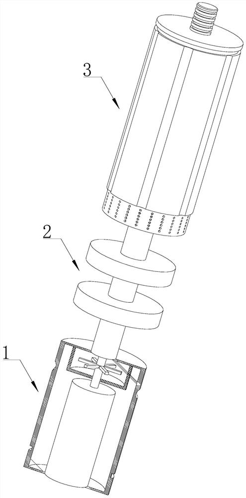
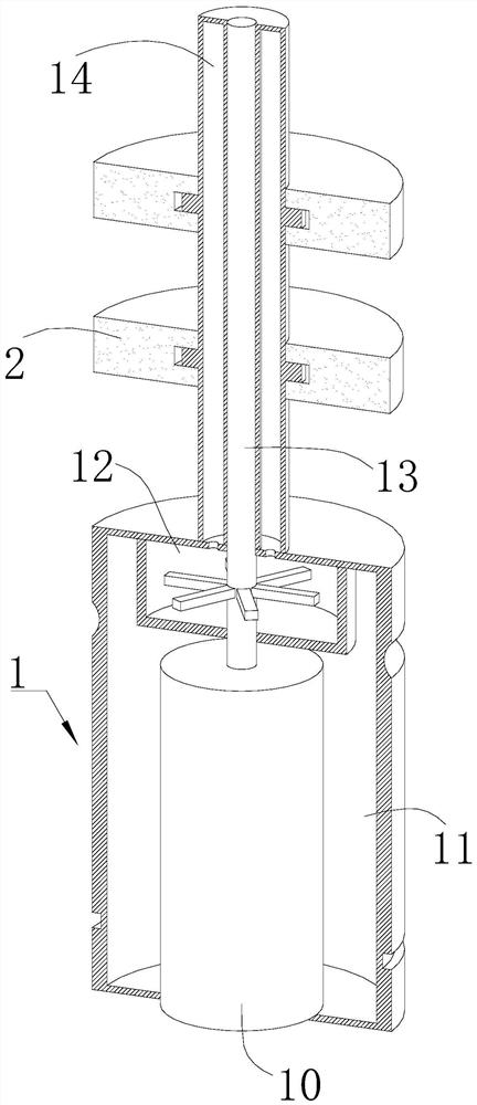
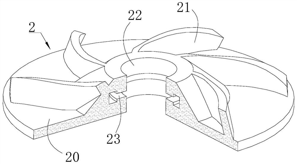
[0038] Specific embodiment one: please refer to Figure 1-6 A deep well pump with reduced starting water resistance, comprising a motor part 1, an impeller 2 and a pumping part 3 arranged coaxially.
[0039] The motor part 1 includes a motor 10, a motor housing 11, a water filling assembly 12 and a shaft sleeve 14;
[0040] The motor 10 is fixedly arranged in the motor casing 11, and the motor casing 11 is provided with a cooling fluid to cool down the power supply 10; the output shaft 13 of the motor 10 runs through the upper wall of the motor casing 11 and is located on the upper side of the motor casing 11;
[0041] The shaft sleeve 14 is sleeved on the outer periphery of the output shaft 13 located on the upper side of the motor housing 11, the shaft sleeve 14 is fixedly connected with the output shaft 13, the shaft sleeve 14 is provided with a flow channel 15, and the outer circumference of the shaft sleeve 14 is provided with at least one stop protrusion Touch 16;
[0...
specific Embodiment 2
[0048] Specific embodiment two: on the basis of specific embodiment one, please refer to Figure 7 A deep well pump with reduced starting water resistance. There are multiple impellers 2, which are sequentially arranged along the output shaft 13 from bottom to top. There are multiple sets of limit synapses 16, which are consistent with the number of impellers 2. The location corresponds to the location of the limiting synapse 16 .
[0049] A plurality of pressure valves 17 are arranged in the flow channel 15, and the number of the pressure valves 17 is consistent with the number of the limit synapses 16. The liquid needs to pass through the pressure valve 17 before entering the corresponding limit synapse 16 .
[0050] The pressure valve 17 is a normally closed part, and the opening threshold of each pressure valve 17 is different. The lower the opening threshold of the pressure valve 17 on the lower side of the flow channel 15, the lower the opening threshold, that is, the w...
specific Embodiment 3
[0052] Embodiment 3: Different from Embodiment 1, the water-filled tank can also communicate with the outside of the motor casing. When the deep well pump is put into the well, the water-filled tank is communicated with the well water, and the well water enters the flow channel to drive the contact to move , wherein, the connection port between the water filling tank and the well water is provided with a filter screen to prevent solid particle impurities from entering the flow channel and causing blockage.
PUM
 Abstract
Description
Claims
Application Information
 - R&D
- Intellectual Property
- Life Sciences
- Materials
- Tech Scout
- Unparalleled Data Quality
- Higher Quality Content
- 60% Fewer Hallucinations
Browse by: Latest US Patents, China's latest patents, Technical Efficacy Thesaurus, Application Domain, Technology Topic, Popular Technical Reports.
© 2025 PatSnap. All rights reserved.Legal|Privacy policy|Modern Slavery Act Transparency Statement|Sitemap|About US| Contact US: help@patsnap.com


