On-machine detection device for measuring aviation blade based on structured light and point cloud acquisition method

A technology for aviation blades and detection devices, which is applied to the point cloud acquisition of aviation blades on-machine detection devices, blade on-machine detection devices and point cloud acquisition fields, can solve the problem of reducing processing efficiency and yield, inability to guide blades online, and offline measurement Low efficiency and other problems, to achieve the effect of improving machining accuracy, avoiding secondary clamping errors, and improving production and testing efficiency

Pending Publication Date: 2022-05-03
HARBIN UNIV OF SCI & TECH
View PDF0 Cites 0 Cited by
  • Summary
  • Abstract
  • Description
  • Claims
  • Application Information

AI Technical Summary

Problems solved by technology

[0004] The purpose of the present invention is to solve the problems of low off-line measurement efficiency in aviation blade processing, inability to guide blade processing online based on measurement data, and cause secondary clamping errors, reducing processing efficiency and yield, and provides a method for measuring aviation blades based on structured light. On-machine detection device and point cloud acquisition method

Method used


Image

  • On-machine detection device for measuring aviation blade based on structured light and point cloud acquisition method
  • On-machine detection device for measuring aviation blade based on structured light and point cloud acquisition method
  • On-machine detection device for measuring aviation blade based on structured light and point cloud acquisition method

Examples


specific Embodiment approach 1

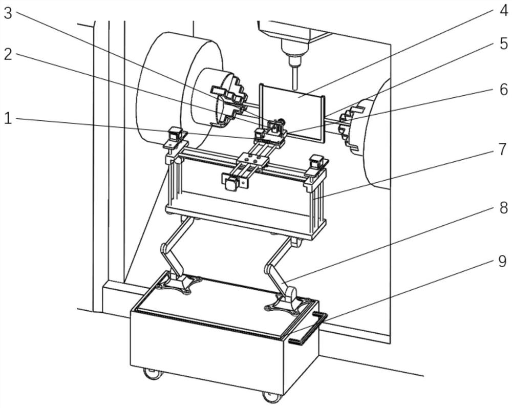
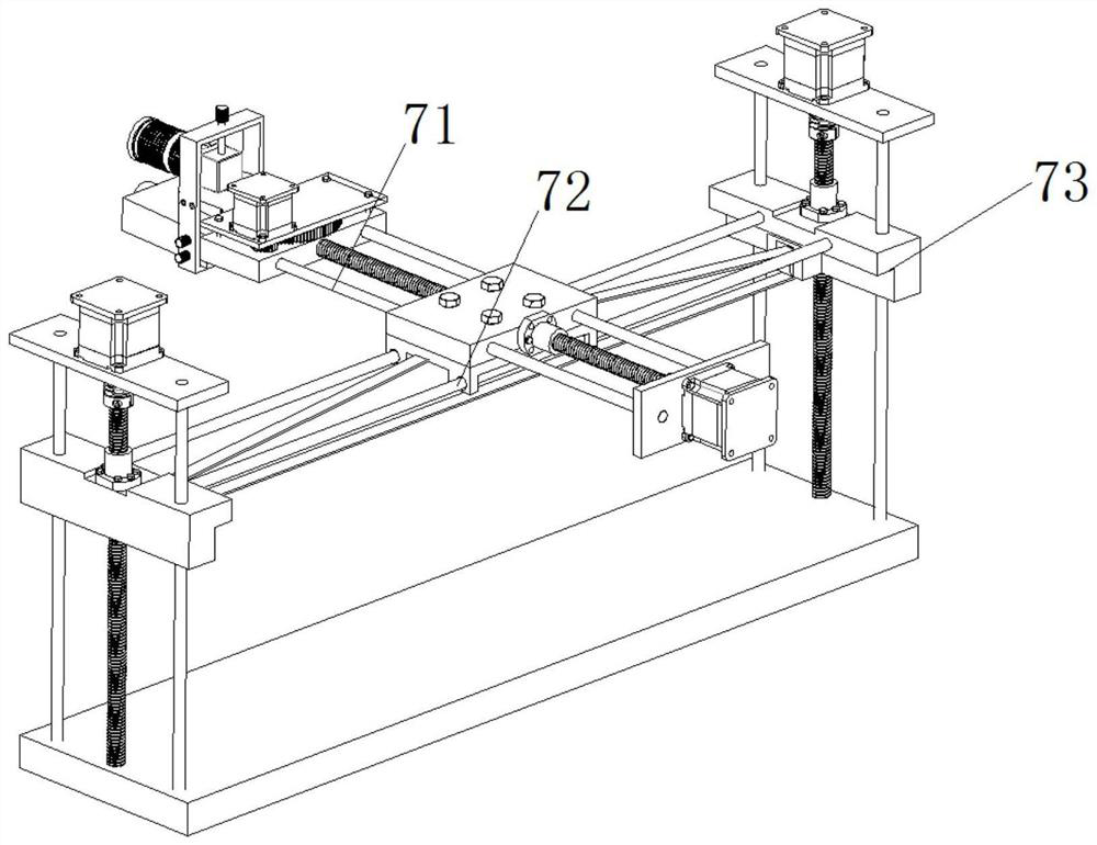
[0024] Specific implementation mode one: combine Figure 1-Figure 4 This embodiment is described. The on-board inspection device for aviation blades based on structured light measurement in this embodiment includes a terminal rotation mechanism 1, a CCD camera 2, a structured light system fixing device 3, a calibration plate 4, a calibration plate fixture 5, The projector 6, the three-axis motion mechanism 7 and the bottom support; the CCD camera 2 and the projector 6 are installed on the structured light system fixing device 3, and the structured light system fixing device 3 is installed on the end rotating mechanism 1, and the end rotating mechanism 1 It is fixedly connected with the three-axis motion mechanism 7, the three-axis motion mechanism 7 is installed on the bottom support, the calibration plate 4 is installed on the calibration plate fixture 5, and the calibration plate fixture 5 is installed on the machine tool chuck. The detection device provided in this embodime...

specific Embodiment approach 2

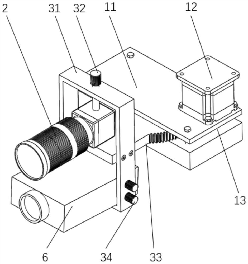
[0026] Specific implementation mode two: combination Figure 1-Figure 2 This embodiment is described. The on-board inspection device for aviation blades based on structured light measurement is given in this embodiment. The structured light system fixing device 3 includes an outer frame 31, a CCD camera locking bolt 32, an intermediate plate 33 and a plurality of projector locks. Tighten bolt 34; CCD camera 2 and projector 6 are installed on the external frame 31 from top to bottom, CCD camera 2 is installed on the external frame 31 by CCD camera locking bolt 32, and projector 6 is by a plurality of projector locking bolts 34 is fixedly installed on the outer frame 31, and one end of the middle plate 33 is fixedly installed on the outer frame 31 by screws, and the middle plate 33 is positioned in the middle of the CCD camera 2 and the projector 6, and the other end of the middle plate 33 is installed on the terminal rotation mechanism ( 1) on. The CCD camera 2 is installed on...

specific Embodiment approach 3

[0028] Specific implementation mode three: combination Figure 1-Figure 2 This embodiment is described. The on-board inspection device for aviation blades based on structured light measurement given in this embodiment, the terminal rotation mechanism 1 includes a stepping motor 12, a motor gear 13, and a fixed plate 11; the fixed plate 11 moves with three axes through bolts The mechanism 7 is fixedly connected, and the other end of the middle plate 33 is rotatably connected and installed on the fixed plate 11. The middle plate 33 installed on one end of the fixed plate 11 is an arc-shaped end plate, and the outer arc surface of the arc-shaped plate is processed with a plurality of teeth. Teeth, stepper motor 12 is installed on the fixed plate 11, and the output end of stepper motor 12 rotating shafts is fixedly set with motor gear 13, and motor gear 13 and middle plate 33 are processed with the arc-shaped end plate tooth engagement of tooth one end. The stepping motor 12 drive...


PUM


Abstract

The invention discloses an aviation blade on-machine detection device based on structured light measurement and a point cloud acquisition method, relates to a blade on-machine detection device and a point cloud acquisition method, and aims to solve the problems that in aviation blade machining, off-line measurement efficiency is low, blade machining cannot be guided on line according to measurement data, secondary clamping errors are caused, and machining precision is high. A CCD camera and a projector are installed on a structured light system fixing device, the structured light system fixing device is installed on a tail end rotating mechanism, the tail end rotating mechanism is fixedly connected with a three-axis movement mechanism, the three-axis movement mechanism is installed on a bottom end support, a calibration plate is installed on a calibration plate clamp, and the calibration plate clamp is fixedly connected with the tail end rotating mechanism. The calibration plate clamp is installed on the machine tool chuck. A calibration plate is installed, and a CCD camera and a projector are clamped; obtaining a distortion correction matrix of the camera; performing rotating shaft calibration on the machine tool spindle; and obtaining point cloud data by using an image distortion correction matrix and a coordinate system conversion matrix. The method belongs to the field of aviation blade on-machine detection.

Description

technical field [0001] The invention relates to a blade on-board detection device and a point cloud acquisition method, in particular to a point cloud acquisition method of an aviation blade on-board detection device, and belongs to the field of blade on-board detection. Background technique [0002] Aeroengines are known as the "Pearl in the Crown" of the modern manufacturing industry, and they play an important role in the fields of aviation and aerospace. As an important part of the aero-engine, the machining accuracy of the aero-blade directly affects the performance, reliability and life of the aero-engine. [0003] The machining accuracy of aviation blades is extremely high, and it is necessary to perform multiple measurements during the machining process to determine whether the accuracy meets the requirements. The traditional measurement method is to remove the blade from the machine tool and move it to a three-coordinate machine for measurement. Since the machinin...

Claims


Application Information

Patent Timeline
Patent Type & Authority Applications(China)
IPC IPC(8): G01B11/00G06T7/80
CPCG01B11/002G06T7/80
Inventor 李茂月卢新元吕虹毓王飞
Owner HARBIN UNIV OF SCI & TECH
Why Eureka
Try Eureka