
A current carrier chip assembly machine and assembly method

A technology for tape and assembler, which is applied to conveyor objects, transportation and packaging, climate sustainability, etc., can solve the problems of poor production quality, difficult to meet processing requirements, low efficiency, etc., to achieve smooth process action, avoid Excessive complexity, to meet the effect of large-scale continuous production and processing

Active Publication Date: 2019-06-25
WUXI AOTEWEI INTELLIGENT EQUIP CO LTD
View PDF4 Cites 0 Cited by
  • Summary
  • Abstract
  • Description
  • Claims
  • Application Information

AI Technical Summary

Problems solved by technology

Therefore, there is an increasing demand for battery assembly and processing in the market, and the market potential is large. At this stage, the corresponding automatic production technology and equipment are still in the initial stage of research and development, resulting in a vacuum period in the domestic market. Therefore, Urgently need a breakthrough in the automation technology of the battery finishing production process to form the ability of continuous automatic production
[0003] Among them, the link of uploading the current carrier is a very important link in the assembly and production process of the battery, that is, after assembling multiple batteries in the shell as a whole in the shelling link, it is necessary to paste the current carrier on both sides of the shell. The traditional shelling method in the industry usually adopts manual method, which has low efficiency and poor production quality, and most of them are produced in small batches
With the gradual increase of market demand, the traditional method of manually uploading tape-outs has been difficult to meet the processing requirements, and there is an urgent need for improvement. At the same time, there is an urgent need for a tape-out assembly machine to meet the needs of large-scale continuous production and processing in the tape-out process. , to achieve high efficiency, high quality and high degree of automation production

Method used


Image

  • A current carrier chip assembly machine and assembly method
  • A current carrier chip assembly machine and assembly method
  • A current carrier chip assembly machine and assembly method

Examples


Embodiment Construction

[0030] The present invention will be described in further detail below according to the drawings and embodiments.

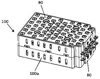
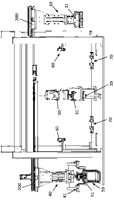
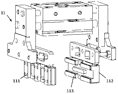
[0031] Such as figure 1 and figure 2 As shown, a current carrier assembly machine according to the embodiment of the present invention includes: an assembly station 20, which is used to undertake the assembly of the loading tape 80 and the casing 100a after the battery is inserted into the shell; the handling and feeding device 10, It is used to transport the shell 100a after the battery is inserted into the shell to the assembly station 20, including the first pneumatic gripper 11 that can be lifted and translated; The chip head 31 obtains the current carrier 80 and places the current carrier 80 on the upper and lower sides of the housing 100a respectively to form the assembly 100; the conveying and unloading device 40 includes a movable pressing assembly 100 The second pneumatic gripper 41.

[0032] The first current carrier is placed on the assembly statio...


PUM


Abstract

The invention relates to a current carrier assembly machine and an assembly method. The current carrier chip assembly machine includes: an assembly station, a conveying and loading device, a current carrier chip loading robot, and a conveying and unloading device. In this assembly method, the first current-carrying chip is placed on the assembly station by the chip-loading robot, and the handling and feeding device transports the shell after the battery is inserted into the case to the assembly station and places it on the first current-carrying chip. Then, the carrier chip loading robot installs the second carrier chip to form an assembly; then the assembly is taken away by the handling and unloading device. The whole process moves smoothly, realizing the upper and lower placement. The upper and lower placement method is more streamlined than the side placement method, which avoids excessive complexity of device design, and at the same time satisfies the need for mass continuous production and processing in the uploading and tape-out process. The demand for high efficiency, high quality and high degree of automation has been realized.

Description

technical field [0001] The invention relates to a current-carrier assembly machine and an assembly method, which belong to the technical field of finishing after battery production. Background technique [0002] With the rapid development of clean energy and the electric vehicle industry, the application of batteries is becoming more and more extensive, especially the application of cylindrical dry batteries in electric vehicles is becoming more and more popular. For example, Tesla's special lithium battery uses thousands of 18650 batteries and assembles them into special battery panels as the power source of the vehicle, and this method is basically recognized and widely used for reference in the industry. Therefore, there is an increasing demand for battery assembly and processing in the market, and the market potential is large. At this stage, the corresponding automatic production technology and equipment are still in the initial stage of research and development, result...

Claims


Application Information

Patent Timeline
Patent Type & Authority Patents(China)
IPC IPC(8): H01M10/058B65G47/90
CPCB65G47/901H01M10/058Y02E60/10Y02P70/50
Inventor 解志俊方慧金岳云
Owner WUXI AOTEWEI INTELLIGENT EQUIP CO LTD
Learn More