Isolation static contact and three-station isolation grounding switch

A static contact and moving contact technology, which is applied to grounding switches, electrical switches, high-voltage/high-current switches, etc. Force deformation, easy insertion and extraction effect

Pending Publication Date: 2022-05-03
HENAN PINGGAO ELECTRIC +1
View PDF1 Cites 0 Cited by
  • Summary
  • Abstract
  • Description
  • Claims
  • Application Information

AI Technical Summary

Problems solved by technology

[0005] The purpose of the present invention is to provide an isolated static contact to solve the technical problem in the prior art that when the arc energy is high, it is easy to cause arc ablation of the conductive contact fingers of the isolated static contact; the purpose of the present invention is also to provide a A three-position isolating grounding switch using the isolating static contact

Method used


Image

  • Isolation static contact and three-station isolation grounding switch
  • Isolation static contact and three-station isolation grounding switch
  • Isolation static contact and three-station isolation grounding switch

Examples


Embodiment 1

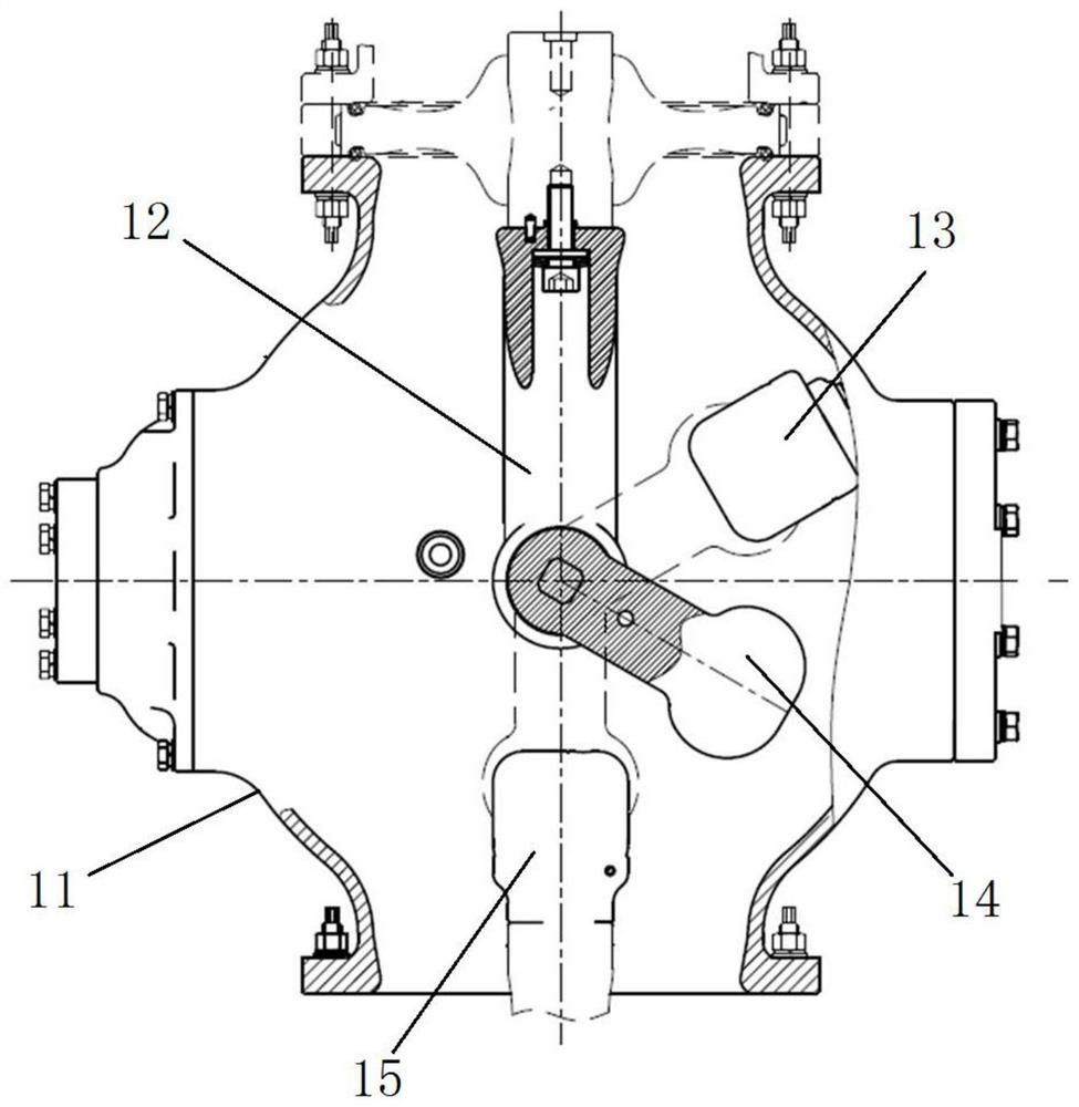
[0055] as Figure 1 As shown, the three-station isolated grounding switch comprises a housing 11, the housing 11 is provided with a moving support 12, the moving support 12 extends in a vertical direction, the upper end of the moving support 12 is fixed at the top of the housing 11, and the lower end of the moving support 12 is connected to the moving contacts 14. The housing is also provided with a grounding static contact 13 and an isolation static contact 15, the grounding static contact 13 is on the right side of the moving support 12, the isolation static contact 15 is below the moving support 12. Wherein, the moving contact 14 is rotated by an insulated torsion bar drive to achieve conductive contact with the isolated static contact 15 or the grounding static contact 13, thereby realizing the isolation and grounding function.

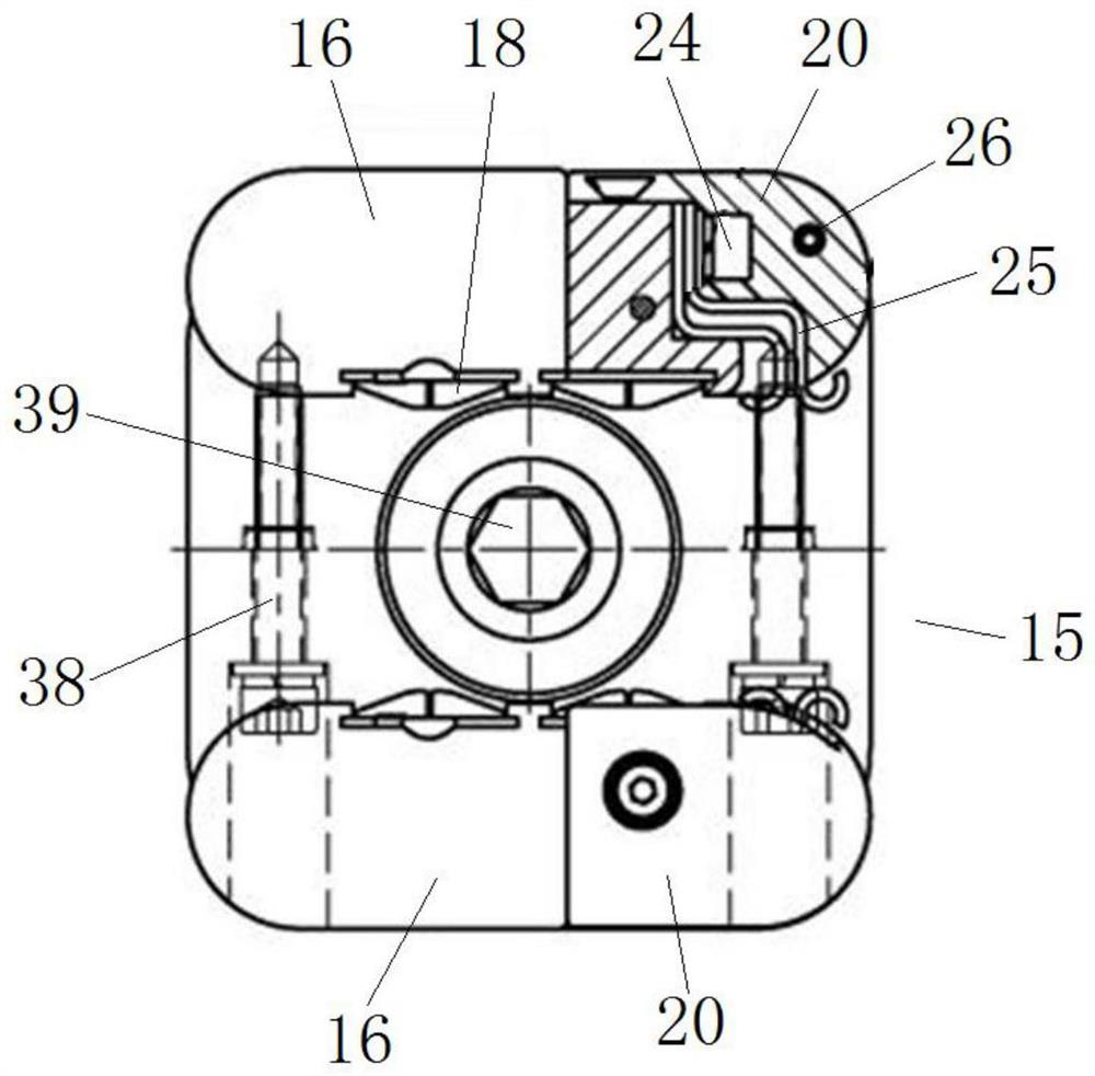
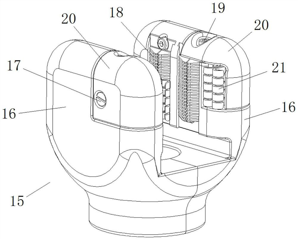
[0056] The moving contact 14 is inserted into the direction of the isolated static contact 15 as the left and right directions. as Figure 2 and Figur...

Embodiment 2

[0071] The difference between the present embodiment and Example 1 is that, in Example 1, the lead arc is a Z-shaped structure, and the arc segment is provided at the end of the lead arc sheet. In the present embodiment, the lead arc is a glyph structure, the arc segment is set in the middle position of the lead arc.

Embodiment 3

[0073] The difference between the present embodiment and Example 1 is that, in Example 1, the two vertical seats are provided with two lead arc plates, and the two lead arc pieces on the same vertical seat are arranged in the left and right directions. In the present embodiment, the two vertical seats are each provided with an arc piece.


PUM


Abstract

The invention relates to an isolation static contact and a three-station isolation grounding switch. The isolation static contact comprises a front vertical seat and a rear vertical seat which are arranged at an interval along the front-back direction, the opposite inner side walls of the two vertical seats are respectively provided with a conductive contact finger, the conductive contact fingers are used for being in conductive contact with the moving contact, the right ends of the two vertical seats are insertion ends for the moving contact to be inserted, the two vertical seats are respectively provided with an arc striking sheet at the insertion ends, and the arc striking sheets are used for being in conductive contact with the moving contact. The arc striking sheet is provided with an arc-shaped section which is bent leftwards or rightwards; and the arc-shaped section is used for being in contact with the moving contact to realize arc striking. In the bus conversion operation process, before the conductive contact fingers of the moving contact and the isolation static contact are separated, the current is mainly passed through the conductive contact fingers; after the moving contact is separated from the conductive contact finger, large current is led to the arc striking sheet through the arc-shaped section, when the moving contact is separated from the arc-shaped section of the arc striking sheet, arcing is started, and at the moment, the arc ablates the arc striking sheet, so that the ablation of the arc to the conductive contact finger can be effectively reduced, and the service life of the isolation static contact is prolonged.

Description

Technical field [0001] The present invention relates to a three-station isolated grounding switch, in particular to a three-station isolated grounding switch isolated static contacts. Background [0002] The transformation and expansion of the old stations of power grid transmission and substations are increasingly used for HGIS switchgear, and the three-station switch with isolated grounding function is an important part of the HGIS equipment, and the relevant technical parameters are increasingly demanding. [0003] At present, the design of three-station isolated grounding switch at home and abroad is mainly divided into two ways: linear motion and rotary motion of moving contacts. For example, the three-station isolated grounding switch disclosed in the Chinese patent document no. CN201629255U includes moving contacts, isolated static contacts and grounding static contacts, and the moving contacts are driven by the rotating shaft for rotational movement. The isolation functi...

Claims


Application Information

Patent Timeline
IPC IPC(8): H01H33/04H01H31/00
CPCH01H33/04H01H31/003
Inventor 孙龙勇刘英英李付永杨光刘刚田利忠高炳灿王福亚姚灿江叶方军王明树周子瑜李森然徐刚徐坤福芦珂王慧慧佟志鹏
Owner HENAN PINGGAO ELECTRIC
Why Eureka
Try Eureka