
Wafer structure

A wafer and chip technology, applied in printing, inking devices, etc., can solve problems such as waste, ineffective reduction of manufacturing costs, waste of blank area, etc.

Active Publication Date: 2022-05-06
MICROJET TECH
View PDF6 Cites 0 Cited by
  • Summary
  • Abstract
  • Description
  • Claims
  • Application Information

AI Technical Summary

Problems solved by technology

If the printable range (printing swath) of an inkjet chip on a wafer structure below 6 inches exceeds 1 inch (inch) or the page width printable range (printing swath) A4 size (8.3 inches (inch)) to Under the requirements of higher high-resolution and higher-speed printing, the number of required inkjet chips will be quite limited when compared to the wafer structure with a limited area below 6 inches. Manufacturing demanded inkjet chips on a wafer structure with a limited area below 6 inches will waste the remaining blank area, and these blank areas will occupy more than 20% of the entire wafer area, which is quite wasteful. cost can not be effectively reduced

Method used


Image

  • Wafer structure
  • Wafer structure
  • Wafer structure

Examples


Embodiment Construction

[0062] Embodiments embodying the features and advantages of this case will be described in detail in the description of the latter paragraph. It should be understood that the present case can have various changes in different aspects without departing from the scope of the present case, and the descriptions and diagrams therein are used for illustration in nature rather than limiting the present case.

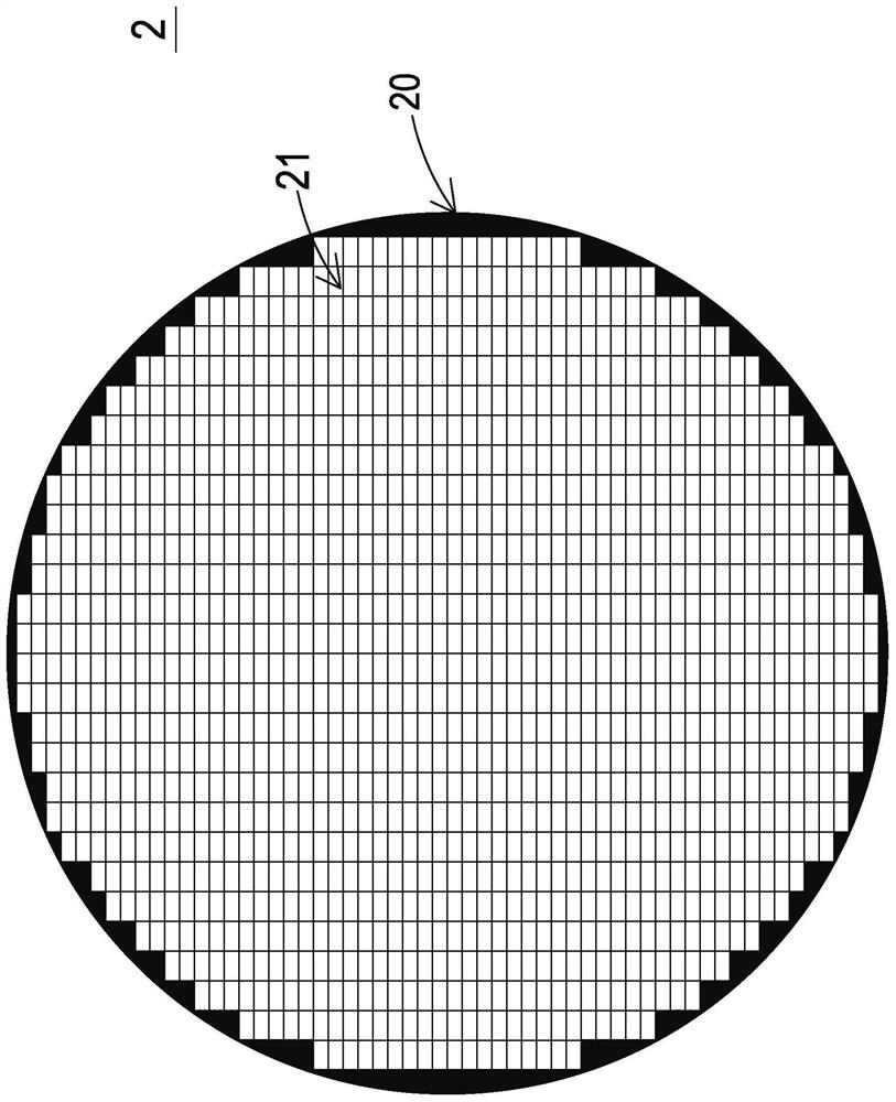
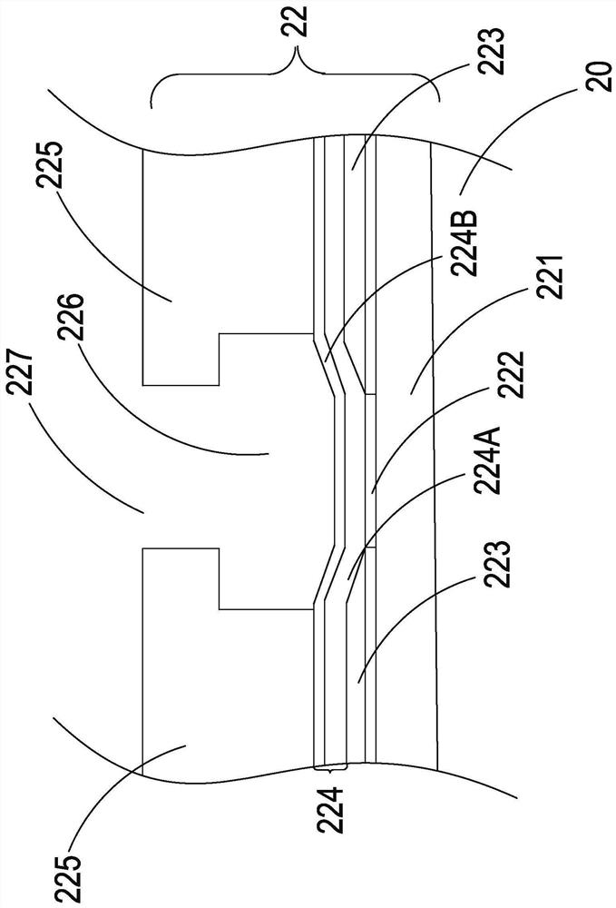
[0063] see figure 1 and figure 2 As shown, the present application provides a wafer structure 2 including: a chip substrate 20 and a plurality of inkjet chips 21 . Wherein the chip substrate 20 is a silicon base material, which is manufactured by a semiconductor manufacturing process of a wafer of at least 12 inches (inch). In a specific embodiment, the chip substrate 20 can be manufactured using a semiconductor manufacturing process of a 12-inch (inch) wafer; or, in another specific embodiment, the chip substrate 20 can be manufactured using a semiconductor process of a 16-...


PUM

PropertyMeasurementUnit
widthaaaaaaaaaa
widthaaaaaaaaaa
widthaaaaaaaaaa

Abstract

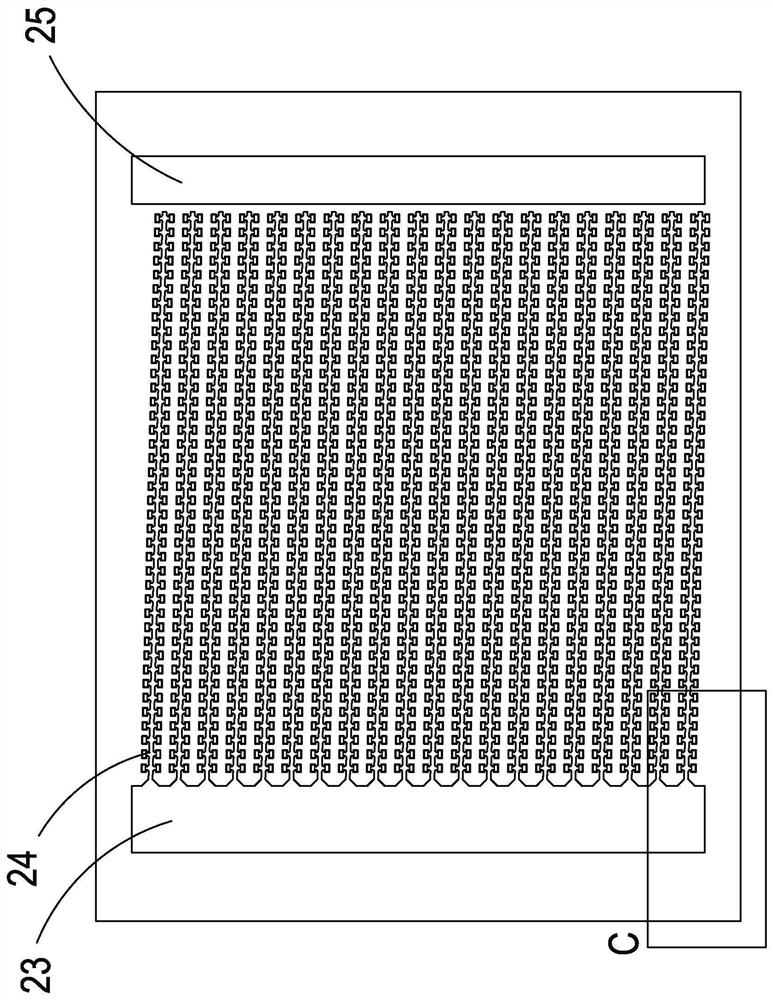
A wafer structure comprises: a chip substrate which is a silicon substrate and is manufactured by a semiconductor process of a wafer of at least 12 inches; the at least one ink-jet chip is directly generated on the chip substrate by a semiconductor manufacturing process and is cut into at least one ink-jet chip to be applied to ink-jet printing; wherein the ink jet chip comprises a plurality of ink droplet generators which are manufactured and generated on the chip substrate through a semiconductor manufacturing process, and the ink jet chip is configured to be a plurality of longitudinal axis array groups which extend along the longitudinal direction and keep a distance between adjacent ink droplet generators, and a plurality of horizontal axis rows configured to extend horizontally and maintain a central step pitch adjacent to the droplet generators, the central step pitch being at least 1 / 600 inch or less.

Description

【Technical field】 [0001] This case relates to a wafer structure, especially a wafer structure of an inkjet chip suitable for inkjet printing produced by semiconductor manufacturing process. 【Background technique】 [0002] In addition to laser printers, inkjet printers are another widely used type of printers currently on the market. They have the advantages of low price, easy operation, and low noise, and can print on various types of paper, such as paper and photo paper. Inkjet media. The printing quality of an inkjet printer mainly depends on factors such as the design of the ink cartridge, especially the design of the inkjet chip to release ink droplets to the inkjet medium is an important consideration in the design of the ink cartridge. [0003] In the highly competitive inkjet printing market, the price of inkjet printers has dropped rapidly as inkjet chips are pursuing higher print quality requirements for high-resolution and higher-speed printing. The manufacturing...

Claims


Application Information

Patent Timeline
Patent Type & Authority Applications(China)
IPC IPC(8): B41J2/14
CPCB41J2/14B41J2/1635B41J2/1642B41J2/1632B41J2/1631B41J2/1646B41J2/14129B41J2/14072B41J2/1404B41J2/0458B41J2/04541B41J2/1603B41J2/14145B41J2/14088B41J2202/13B41J2/1601B41J2/14024B41J2202/11
Inventor 莫皓然张英伦戴贤忠黄启峰韩永隆李伟铭
Owner MICROJET TECH
Learn More