Millimeter wave module circuit and terminal equipment

A millimeter wave and module technology, applied to circuits, electrical components, antennas, etc., can solve problems such as small area, reduced antenna array gain, and poor performance of millimeter wave module circuits

Active Publication Date: 2022-05-06
HONOR DEVICE CO LTD
View PDF7 Cites 1 Cited by
  • Summary
  • Abstract
  • Description
  • Claims
  • Application Information

AI Technical Summary

Problems solved by technology

[0003] However, due to the increasing number of electronic devices integrated on the terminal equipment, the area available for antenna array layout on the terminal equipment is also becoming smaller and smaller; thus, the number of antennas included in the antenna array layout in this area The number of antennas included in some antenna arrays in the millimeter wave module circuit is less than the number of antennas in other antenna arrays
The gain of the antenna array is usually related to the number of antennas included in the antenna array. As the number of antennas decreases, the gain of the antenna array decreases; resulting in poor performance of the mmWave module circuit in the area covered by the antenna array

Method used


Image

  • Millimeter wave module circuit and terminal equipment
  • Millimeter wave module circuit and terminal equipment
  • Millimeter wave module circuit and terminal equipment

Examples


example 1

[0092] A first processing unit connected to all the first antennas 1110 in the first antenna array 1100 is any one of the two first processing units, that is to say, all the first antennas 1110 are connected to the second antenna 1210 Multiplexing the first processing unit.

[0093] In Example 1, when the number N of first antennas 1110 is greater than 2*M, the number of multiple first processing units is N; when the number N of first antennas 1110 is less than 2*M, the number of multiple first processing units The quantity is 2*M.

example 2

[0095] A first processing unit 1310 connected to one or more first antennas 1110 in the first antenna array 1100 is any one of the two first processing units 1310 connected to the second antenna 1210, that is to say, the first processing unit 1310 connected to the second antenna 1210 Some of the first antennas 1110 and the second antennas 1210 in the antenna array 1100 are multiplexed by the first processing unit 1310 .

[0096] In Example 2, when the number N of first antennas 1110 is greater than 2*M, the number of multiple first processing units is greater than N; when the number N of first antennas 1110 is less than 2*M, the number of multiple first processing units The number is greater than 2*M.

example 3

[0098] The second antenna 1210 is connected to two first processing units, and one first processing unit connected to all the first antennas 1110 in the first antenna array 1100 is one of the two first processing units connected to the second antenna 1210 Any one, that is to say, all the first antennas 1110 and the second antenna 1210 are multiplexed with the first processing unit.

[0099] In Example 3, when the number of first antennas 1110 is N=2*M, that is to say, the number of first antennas 1110 is twice the number of second antennas 1210, then the number of multiple first processing units is N or 2*M.

[0100] Exemplarily, if the number of first antennas 1110 is 4 and the number of second antennas 1210 is 2, then the number of first processing units in the processing module is 4.

[0101] In the embodiment of the present application, the number of the first antenna is twice the number of the second antenna, and the second antenna is connected to two first processing un...


PUM


Abstract

The embodiment of the invention is applicable to the technical field of terminals, and provides a millimeter wave module circuit and terminal equipment, the millimeter wave module circuit comprises a first antenna array, a second antenna array and a processing module, the first antenna array comprises N first antennas, the second antenna array comprises M second antennas, and N is greater than M; the processing module comprises a plurality of first processing units, each first antenna in the N first antennas is connected with each first processing unit, each second antenna in the M second antennas is connected with two different first processing units, and each first processing unit comprises a power amplifier; the processing module is used for sending a first signal to the first antenna through the first processing unit; and the processing module is used for sending the second signal to the second antenna in a differential feed manner through two different first processing units, so that the signal coverage range of the second antenna array is enlarged, and the performance of the millimeter wave module in the coverage area of the second antenna array is improved.

Description

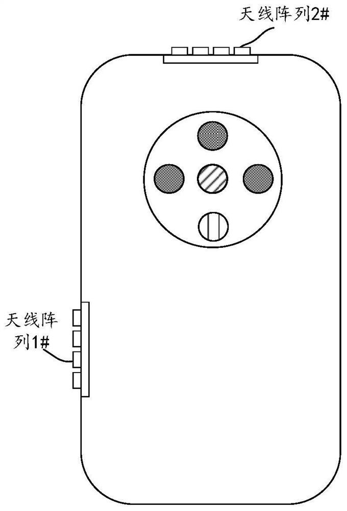
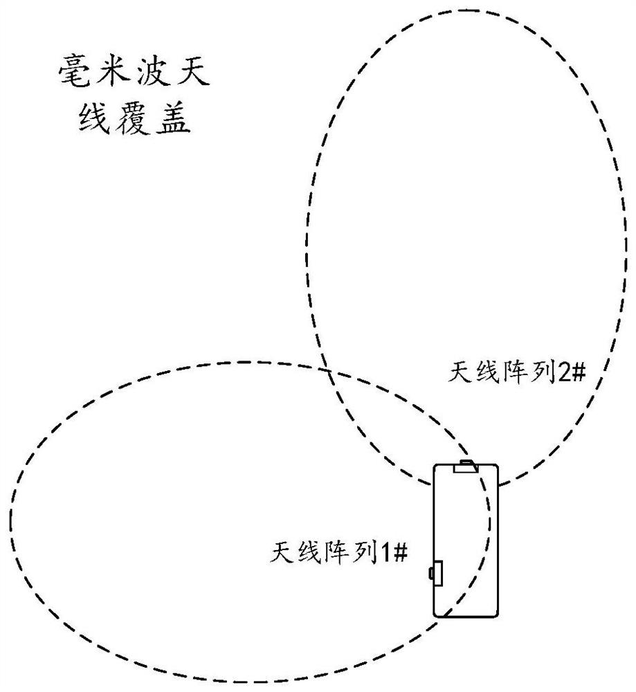
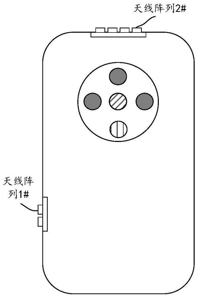
technical field [0001] The embodiments of the present application relate to the field of terminal technologies, and in particular to millimeter wave module circuits and terminal equipment. Background technique [0002] The millimeter wave antenna module, referred to as "millimeter wave module circuit", is a device that includes a millimeter wave radio frequency (Radio Frequency, RF) front end and an antenna array. Due to the high attenuation of millimeter waves during radiation, the coverage area of ​​millimeter wave radiation is usually small. In order to expand the coverage of millimeter wave radiation, multiple antenna arrays are usually set up in different directions on the terminal equipment, such as figure 1 As shown, the coverage of the millimeter wave radiation can be superimposed on each other in different directions to expand the coverage of the millimeter wave radiation. Usually, the number of antennas in the multiple antenna arrays is set to be the same accordi...

Claims


Application Information

Patent Timeline
IPC IPC(8): H01Q21/00H01Q3/34H01Q3/28H01Q1/24H01Q1/00H01Q1/50
CPCH01Q21/00H01Q3/34H01Q3/28H01Q21/0006H01Q1/002H01Q1/243Y02D30/70H01Q21/28H01Q21/08H01Q3/36H04M1/0266
Inventor 江成王宇曲增朝盆天玉刘东平
Owner HONOR DEVICE CO LTD
Why Eureka
Try Eureka