
Data acquisition device for computer network engineering

A computer network and data acquisition technology, applied in the direction of casing/cabinet/drawer parts, separation method, electrical equipment casing/cabinet/drawer, etc., can solve data loss, short circuit of components and equipment, damage to the motherboard, etc. Problems

Pending Publication Date: 2022-05-06
宿迁市数博软件科技有限公司
View PDF0 Cites 0 Cited by
  • Summary
  • Abstract
  • Description
  • Claims
  • Application Information

AI Technical Summary

Problems solved by technology

[0003] When the existing data acquisition device is used for a long time, it will generate a lot of heat, and it needs to be cooled down. Due to the limitation of the installation environment of the acquisition device, the acquisition device works in a dark and humid computer room. If the air is directly introduced into the The device cools it down, and the humid air will damage the components on the motherboard, causing a short circuit of the device, and there is a risk of data loss

Method used


Image

  • Data acquisition device for computer network engineering
  • Data acquisition device for computer network engineering
  • Data acquisition device for computer network engineering

Examples


Embodiment 1

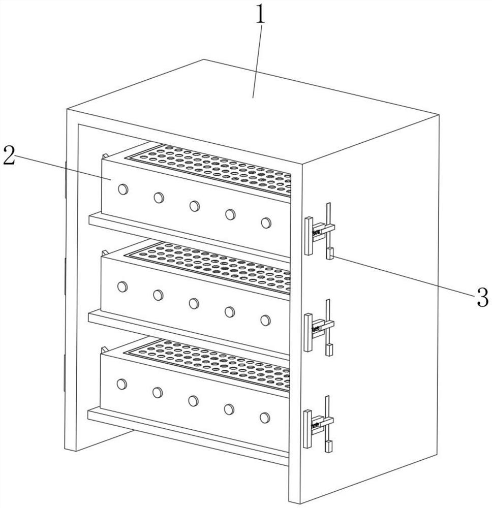
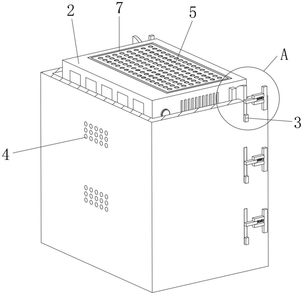
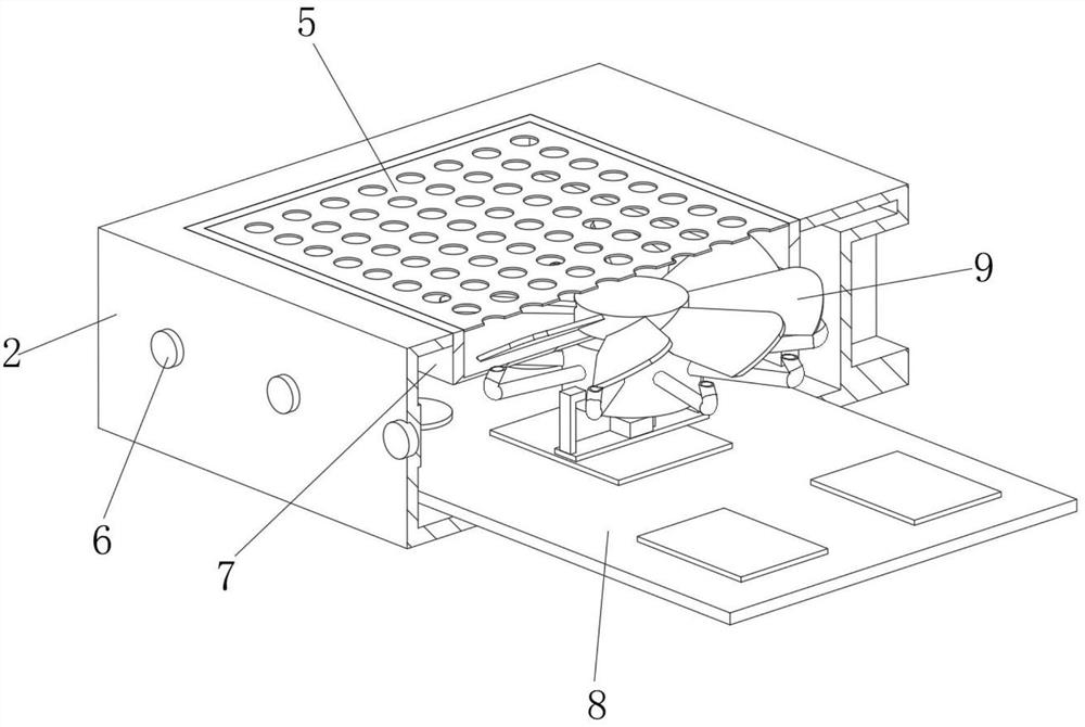
[0034] refer to Figure 1-5 The shown data acquisition device for computer network engineering includes a cabinet box 1 and a device body 2. The device body 2 is installed inside the cabinet box 1. The back side of the cabinet box 1 is provided with ventilation holes 4. The upper surface of the device body 2 is There is a groove 7, the inner wall of the groove 7 is provided with a filter screen 5, the front of the device main body 2 is provided with a signal light 6, the inner bottom wall of the device main body 2 is provided with a control board 8, and the lower surface of the groove 7 is provided with a dehumidifier The heat dissipation mechanism 9 and the left and right sides of the cabinet box 1 are provided with a positioning mechanism 3 .

[0035]By virtue of the above-mentioned structure, it is convenient to carry out ventilation by setting the ventilation hole 4, by setting the filter screen 5, the first filtering of the air is realized, by setting the signal lamp 6, t...

Embodiment 2

[0037] Based on the above-mentioned embodiment 1, the dehumidification and heat dissipation mechanism 9 includes a fixed cylinder 902 arranged on the lower surface of the groove 7, the upper surface of the fixed cylinder 902 and the inner bottom wall of the groove 7 are provided with the same avoidance hole, and the inner wall of the avoidance hole is set There is a protective cover plate 904, and a plurality of air inlet holes 903 are opened on the surface of the protective cover plate 904. The rotating shaft 907 is avoided by setting the avoidance hole, the dehumidified air entering the fixed cylinder 902 is guided by the air inlet hole 903, and the vibrating slide plate 906 is formed by setting the protective sleeve plate 904 and the fixed cylinder 902. confined space.

Embodiment 3

[0039] Based on the above-mentioned embodiment 1 or 2, the inner bottom wall of the groove 7 is provided with a plurality of small holes, and the inner wall of the small holes is provided with a curved pipe 905, and the bottom end of the curved pipe 905 runs through the inner wall of the fixed cylinder 902 . By arranging small holes, a fixed space is provided for the curved pipe 905 to be installed, and by arranging the curved pipe 905, the outside air is guided.


PUM


Abstract

The invention discloses a data acquisition device for computer network engineering, and relates to the field of data acquisition devices, the data acquisition device comprises a cabinet box and a device main body, the device main body is installed in the cabinet box, the back of the cabinet box is provided with vent holes, the upper surface of the device main body is provided with a groove, and the inner wall of the groove is provided with a filter screen. According to the invention, ventilation holes are arranged to facilitate ventilation, a filter screen is arranged to filter air for the first time, a signal lamp is arranged to feed back the normal working condition of the device main body, and a dehumidification heat dissipation mechanism is arranged to dehumidify the air, so that short circuit of equipment components caused by moisture of the air entering the device main body is prevented; by arranging the positioning mechanism, the device main body is limited, meanwhile, the device main body is conveniently taken down from the cabinet box, and by means of the structure, air is dehumidified, and the situation that wet air damages components on a mainboard and causes short circuit of equipment is prevented.

Description

technical field [0001] The invention relates to the field of data acquisition devices, in particular to a data acquisition device for computer network engineering. Background technique [0002] Data Acquisition (DAQ) refers to the automatic collection of non-electric or electrical signals from analog and digital units under test such as sensors and other devices to be tested, and sends them to the host computer for analysis and processing. The data acquisition system is a flexible and user-defined measurement system combined with measurement software and hardware products based on computers or other special test platforms. [0003] When the existing data acquisition device is used for a long time, it will generate a lot of heat, and it needs to be cooled down. Due to the limitation of the installation environment of the acquisition device, the acquisition device works in a dark and humid computer room. If the air is directly introduced into the The device cools it down, and...

Claims


Application Information

Patent Timeline
IPC IPC(8): H05K7/20H05K5/02B01D53/26B01D46/10
CPCH05K7/20181H05K7/20136H05K5/0217B01D46/10B01D53/26B01D2257/80
Inventor 蔡志勇
Owner 宿迁市数博软件科技有限公司
Learn More