Folding desk capable of realizing afternoon nap function

A technology of folding desks, which is applied to desks with variable table heights, reconfigurable furniture, legs of general furniture, etc. It can solve the problems of students who cannot support their legs and students who cannot take a comfortable lunch break, etc., and increase the area Effect

Pending Publication Date: 2022-05-10
叶芳
View PDF1 Cites 0 Cited by
  • Summary
  • Abstract
  • Description
  • Claims
  • Application Information

AI Technical Summary

Problems solved by technology

[0005] In order to overcome the shortcomings that the existing nap desks cannot support the students' legs when they are used for naps, so that students cannot take a nap comfortably, the technical problem to be solved is to provide a table that is convenient for students to place their legs. Folding desk for nap function

Method used


Image

  • Folding desk capable of realizing afternoon nap function
  • Folding desk capable of realizing afternoon nap function
  • Folding desk capable of realizing afternoon nap function

Examples


Embodiment 1

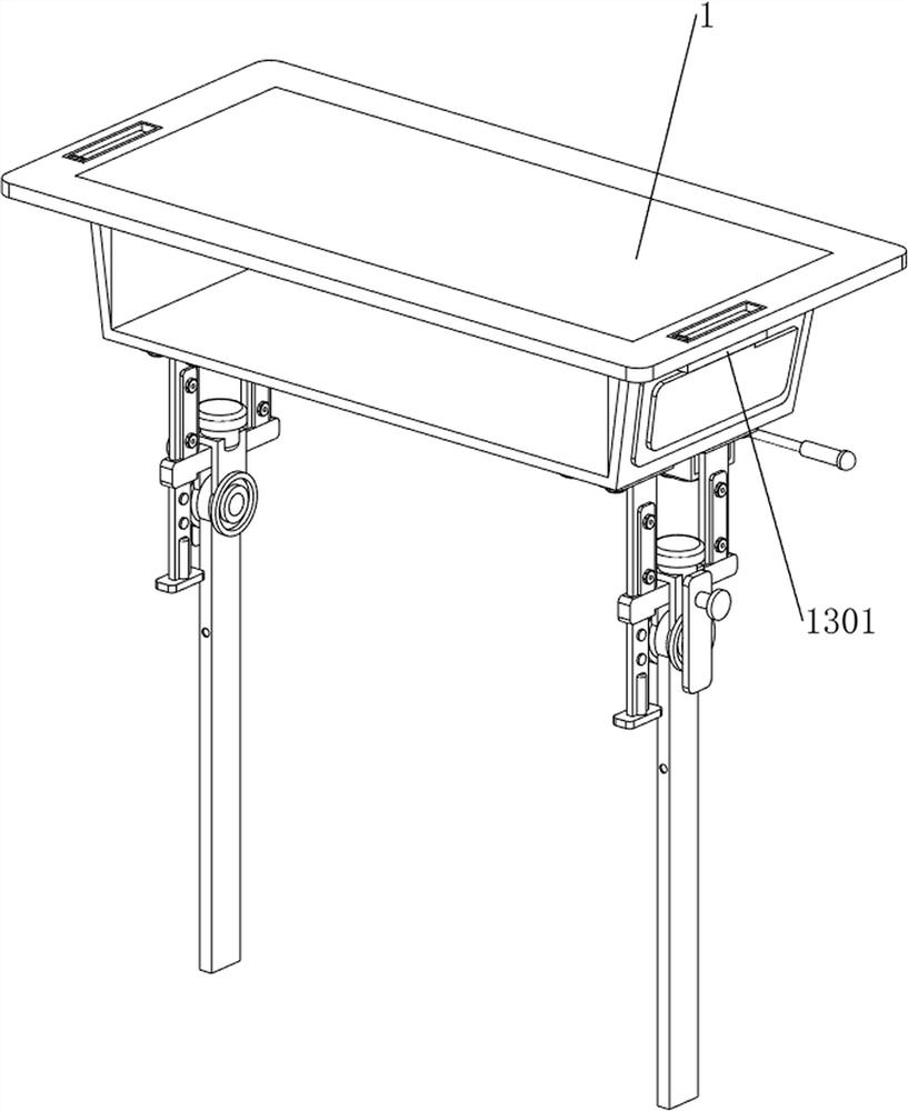
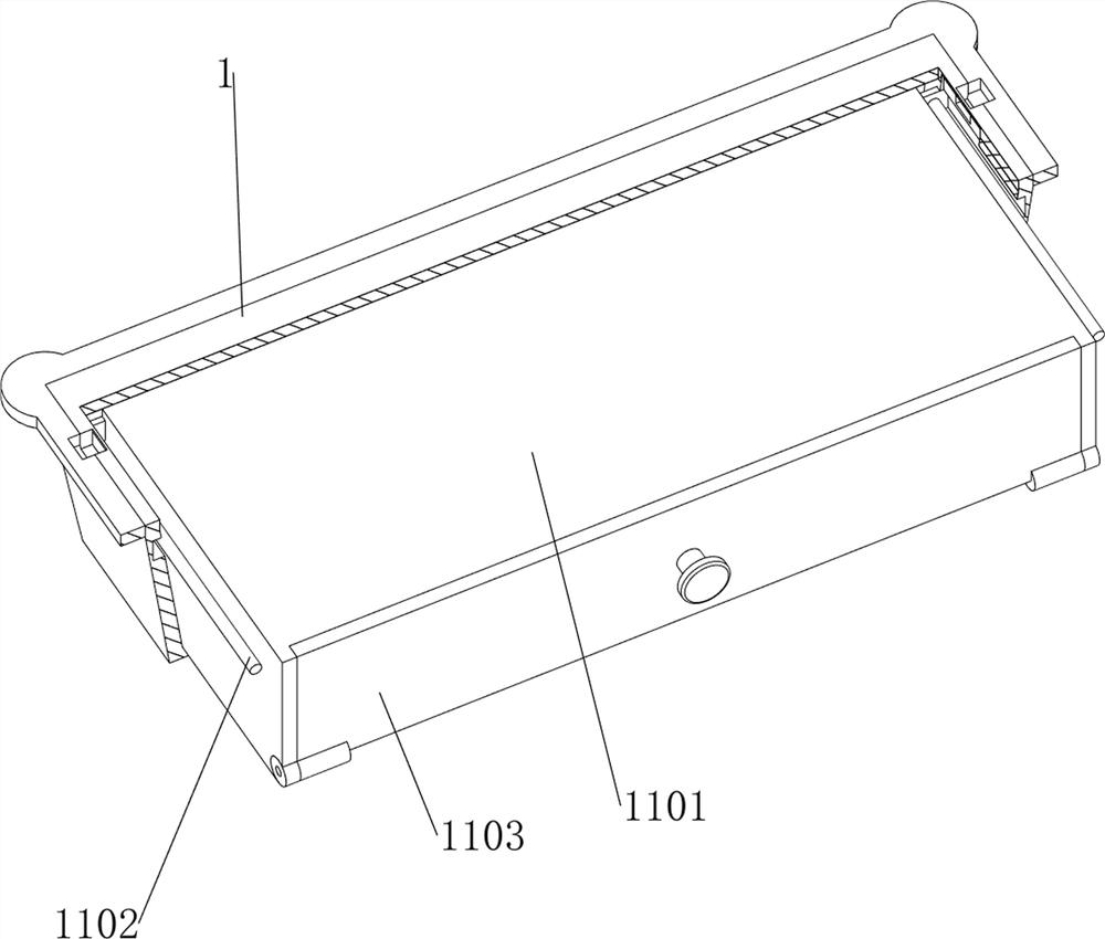
[0040] see Figure 1-Figure 6 As shown, a folding desk that can realize the nap function includes a placement frame 1, a connecting plate 2, a supporting plate 3, a rotating plate 4, a first connecting rod 5, a first locking rod 6, and a first spring 7 , the adjustment mechanism 8 and the foot mechanism 9, the left and right sides of the bottom of the placement frame 1 are provided with connecting plates 2 by means of screw connections, and the front sides of the bottoms of the two connecting plates 2 are welded with supporting plates 3, and the lower parts of the two connecting plates 2 The rotation plate 4 is arranged in a rotating manner, the first connecting rod 5 is arranged on the back side of the bottom of the two connecting plates 2, and the first locking rod 6 is slidingly arranged on the two first connecting rods 5, and the first locking rod 6 The clamping rod 6 is inserted between the adjacent connecting plate 2 and the rotating plate 4, the first spring 7 is wound ...

Embodiment 2

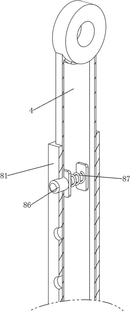
[0043] see Figure 2-Figure 4 As shown, on the basis of Embodiment 1, the adjustment mechanism 8 includes a first connecting frame 81, a rotating foot frame 82, a second connecting rod 83, a first locking plate 84, a second spring 85, a telescopic rod 86 and The third spring 87, the first connecting frame 81 is slidingly arranged on the two rotating plates 4, seven round holes are evenly spaced on the front side of the first connecting frame 81, and the bottom ends of the two first connecting frames 81 are all rotating A swivel stand 82 is provided, and second connecting rods 83 are welded symmetrically up and down on the opposite sides of the two first connecting frames 81 , and first locking plates are slidingly arranged between the two adjacent second connecting rods 83 84, the first clamping plate 84 is inserted between the adjacent swivel stand 82 and the first connecting frame 81, the first clamping plate 84 is in contact with the first clamping rod 6, and the inside of ...

Embodiment 3

[0048] see figure 1 , Figure 7 with Figure 8 As shown, on the basis of Embodiment 1, a locking mechanism 10 is also included. The locking mechanism 10 can limit the rotation rod 92. The locking mechanism 10 includes a sliding sleeve 101, a second locking rod 102 and a fourth spring. 103, two sliding sleeves 101 are welded at the middle and lower parts of the front side of the two first connecting frames 81, and the second locking rod 102 is slidably arranged on the two sliding sleeves 101, and the second locking rod 102 and the lower part of the rotating rod 92 Engaged, the fourth spring 103 is wound between the front part of the second clamping rod 102 and the adjacent sliding sleeve 101, and the initial state of the fourth spring 103 is a stretched state.

[0049] The rotating rod 92 rotates downward by 90 degrees and no longer squeezes the second clamping rod 102, and the fourth spring 103 then resets and drives the second clamping rod 102 to slide inward to lock the ro...


PUM


Abstract

The invention relates to a folding desk, in particular to a folding desk capable of realizing an afternoon nap function. The invention provides the folding desk capable of realizing the afternoon nap function, which is convenient for a student to place two legs. The folding desk capable of achieving the afternoon nap function comprises a containing frame, and connecting plates are arranged on the left side and the right side of the bottom of the containing frame; the supporting plates are arranged on the front sides of the bottoms of the two connecting plates; the rotating plates are rotationally arranged at the lower parts of the two connecting plates; and the first connecting rods are arranged on the back sides of the lower parts of the two connecting plates. A user pushes the rotating foot stool to rotate downwards by 90 degrees to be in contact with the ground to support the rotating plates, and due to the fact that the height of the placing frame and the height of the stool are located on the same horizontal plane, the user places the stool between the two rotating plates, and then the user lies on the stool and the placing frame to have a noon break.

Description

technical field [0001] The invention relates to a folding desk, in particular to a folding desk capable of realizing the nap function. Background technique [0002] Nowadays, students are under more and more pressure, and their homework is getting more and more intense. In order to save time, many students take a nap in the classroom at noon, but it is not comfortable to sleep on a smooth desk, which leads to poor sleep quality for students in the nap, which is easy to affect Learning efficiency. [0003] The patent authorization notification number is CN211533264U, which discloses a folding nap desk. The nap desk includes a desk cabinet, a column, a table base and a dual-purpose pallet. The utility model comprises a high column and a low column fixedly connected with the base of the table, and the two ends of the desktop are respectively hinged with the high column and the dual-purpose supporting plate. When the nap desk is used for a nap, the student adjusts the desktop ...

Claims


Application Information

Patent Timeline
Patent Type & Authority Applications(China)
IPC IPC(8): A47B41/00A47B41/02A47B9/00A47B13/02A47B85/00
CPCA47B41/00A47B41/02A47B9/00A47B13/02A47B85/00
Inventor 叶芳
Owner 叶芳
Why Eureka
Try Eureka