Knee operation auxiliary bed for orthopedics department

An auxiliary bed and knee technology, applied in the field of auxiliary beds, can solve the problems of low accuracy, limited adjustment angle of auxiliary devices, and inability to fix the position of the patient's legs, etc., and achieve the effect of high accuracy

Pending Publication Date: 2022-05-10
黄祺
View PDF0 Cites 0 Cited by
  • Summary
  • Abstract
  • Description
  • Claims
  • Application Information

AI Technical Summary

Problems solved by technology

[0004] In order to overcome the disadvantages of the existing auxiliary device that the adjustment angle is limited, fine-tuning cannot be performed, the accuracy is not high, and it can only act as a simple support for the patient's leg, and cannot fix the position of the patient's leg. Technical problems: Provides an orthopedic knee surgery auxiliary bed that can fine-tune the bending degree of the patient's leg and can limit and fix the patient's leg

Method used


Image

  • Knee operation auxiliary bed for orthopedics department
  • Knee operation auxiliary bed for orthopedics department
  • Knee operation auxiliary bed for orthopedics department

Examples


Embodiment 1

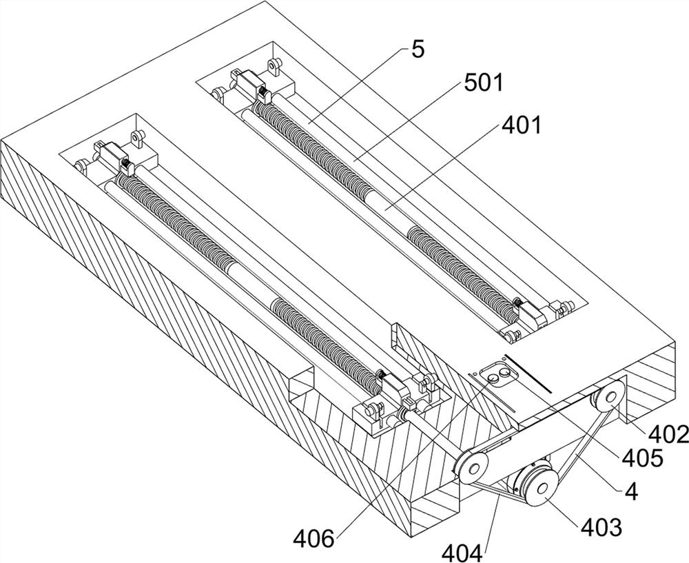
[0073] An orthopedic auxiliary bed for knee surgery, such as Figure 1-Figure 6 As shown, it includes a leg 1, a bed body 2, a servo motor 3, a drive assembly 4, a movable assembly 5, a limit assembly 6, a first rotating shaft 7, a first support plate 8, a second support plate 9, and a connecting block 10 and the first rotary rod 11, the bottom of the bed body 2 is provided with a leg 1, the middle of the right side of the bottom of the bed body 2 is provided with a servo motor 3, the inner right part of the bed body 2 is provided with a drive assembly 4, and the drive assembly 4 is provided with a movable assembly 5. The movable assembly 5 is provided with a limit assembly 6, and the movable assembly 5 is provided with a first rotating shaft 7 symmetrically rotating, and the number of the first rotating shafts 7 is 8, and the inside of the first rotating shaft 7 on the left is provided with a first rotating shaft. Support plates 8, the number of the first support plates 8 is ...

Embodiment 2

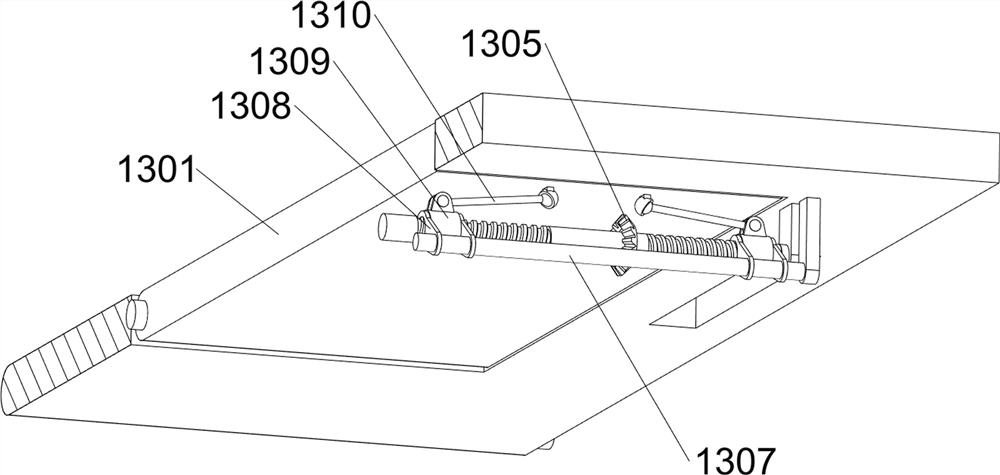
[0079] On the basis of Example 1, such as figure 1 , Figure 6 , Figure 7 , Figure 8 , Figure 9 , Figure 10 , Figure 11 and Figure 12 As shown, it also includes a stabilizing assembly 12. The stabilizing assembly 12 includes a limiting plate 1201, a sector block 1202, a second rotating rod 1203, a contact rod 1204, a first clamping rod 1205 and a compression spring 1206. The middle part of the second supporting plate 9 is front and rear Both sides are slidingly provided with limit plates 1201, the inner side of the first rotating shaft 7 on the right is provided with fan-shaped blocks 1202, the number of fan-shaped blocks 1202 is 4, and the inner side of the first rotating shaft 7 on the right side is equipped with a second rotating rod 1203, the number of the second rotating rod 1203 is 4, the second rotating rod 1203 is slidingly matched with the limit plate 1201, and the inner side of the mounting block 502 on the right side is equipped with a contact rod 1204 s...


PUM


Abstract

The invention relates to an auxiliary bed, in particular to a knee operation auxiliary bed for the orthopedics department. According to the knee operation auxiliary bed for the orthopedics department, the bending degree of the legs of a patient can be finely adjusted, and the legs of the patient can be limited and fixed. The knee operation auxiliary bed for the orthopedics department comprises supporting legs and a bed body, and the supporting legs are installed at the bottom of the bed body; the servo motor is mounted in the middle of one side of the bottom of the bed body; the driving assembly is mounted on one side in the bed body; and the movable assembly is mounted on the driving assembly. Under the cooperation of the driving assembly, the movable assembly, the limiting assembly, the first supporting plate and the second supporting plate, the first supporting plate and the second supporting plate can be driven to rotate by controlling a servo motor to rotate forwards and backwards according to the needs of a doctor, so that the legs of a patient are driven to bend, the purpose of adjusting the bending degree of the legs is achieved, and the precision is high.

Description

technical field [0001] The invention relates to an auxiliary bed, in particular to an orthopedic auxiliary bed for knee surgery. Background technique [0002] When doctors perform knee surgery on orthopedic patients, in order to facilitate the operation, the patient's legs need to be supported and fixed at different angles, which requires the use of auxiliary devices to effectively support and fix the patient's legs. [0003] The structure and function of the existing auxiliary device is relatively simple. When adjusting the bending degree of the patient's leg, it can only be adjusted according to different clamping hole positions. The adjustment angle is limited, fine adjustment is not possible, and the accuracy is not high. And it can only act as a simple support for the patient's leg, and cannot fix the position of the patient's leg, causing the patient's leg to move during the operation, thereby affecting the operation. An orthopedic knee surgery auxiliary bed that fine...

Claims


Application Information

Patent Timeline
IPC IPC(8): A61G13/00A61G13/12A61G13/10
CPCA61G13/00A61G13/1245A61G13/128A61G13/10A61G2210/10
Inventor 黄祺
Owner 黄祺
Why Eureka
Try Eureka