Disinfection wardrobe for hospital nurses and use method of disinfection wardrobe

A technology for nurses and hospitals, applied in the field of disinfection wardrobes for hospital nurses, can solve the problems of waste of resources, non-targeted, poor disinfection effect, etc., achieve the effect of reducing waste and wide application range

Pending Publication Date: 2022-05-10
中国人民解放军总医院第八医学中心
View PDF1 Cites 0 Cited by
  • Summary
  • Abstract
  • Description
  • Claims
  • Application Information

AI Technical Summary

Problems solved by technology

[0004] In the prior art, the ultraviolet light is generally used to disinfect the nurse's clothes, but the ultraviolet light is placed on the inner wall of the cabinet, and when there are many clothes in the wardrobe, it cannot be irradiated on each piece of clothing, and the disinfection effect is relativel

Method used


Image

  • Disinfection wardrobe for hospital nurses and use method of disinfection wardrobe
  • Disinfection wardrobe for hospital nurses and use method of disinfection wardrobe
  • Disinfection wardrobe for hospital nurses and use method of disinfection wardrobe

Examples


Embodiment 1

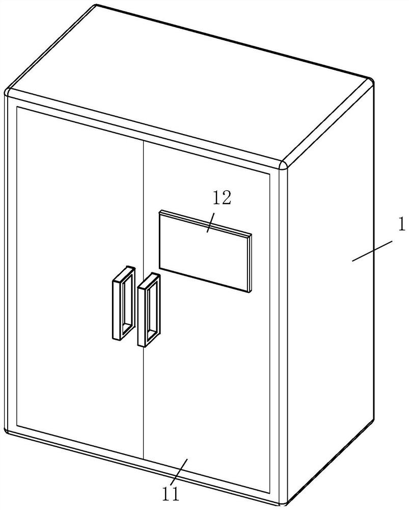
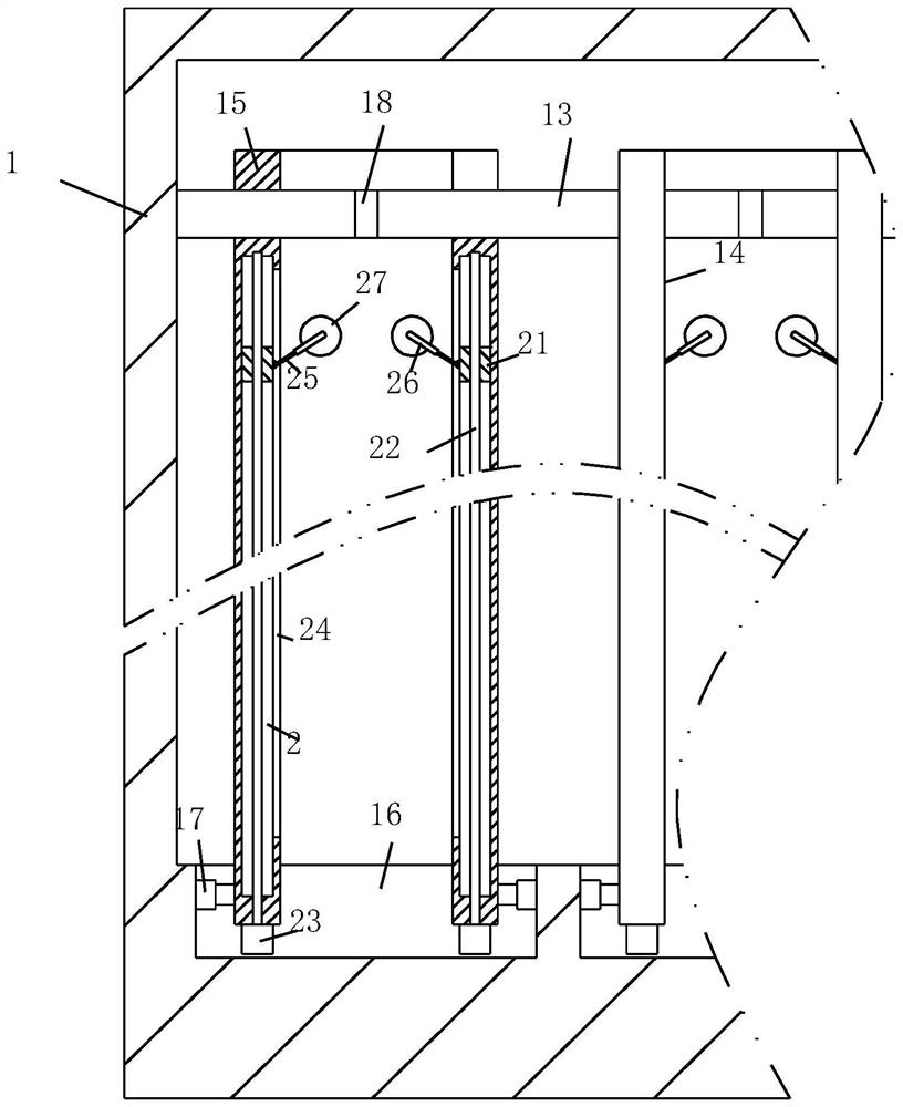
[0035] Such as Figure 1 to Figure 4 As shown, a kind of disinfection wardrobe for hospital nurses according to the embodiment of the present invention includes a cabinet body 1; a pair of symmetrically distributed cabinet doors 11 are provided on the side wall of the cabinet body 1; A display screen 12; a hanging rod 13 is fixedly connected to the inner wall of the cabinet body 1; a group of disinfection components 14 are arranged on the cabinet body 1; the disinfection component 14 includes a fixing plate 15 and a first groove 16; the cabinet body 1 A group of first grooves 16 are provided at the bottom of the body 1; fixed plates 15 are fixedly connected to the side walls on both sides of the first grooves 16 through electric telescopic rods 17; the fixed plates 15 are slidably connected to the hanging rods 13 A pair of said fixed plates 15 opposite faces are equipped with ultraviolet lamps 19; said hanging rods 13 are provided with a group of hanging grooves 18; said hangi...

Embodiment 2

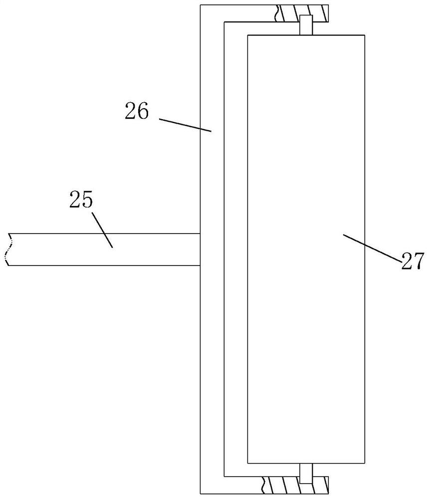
[0044] Such as Figure 7 As shown in Comparative Example 1, another embodiment of the present invention is: a group of cleaning brushes 4 is fixedly attached to the side wall of the U-shaped plate 26; In contact with each other, and the cleaning brush 4 is a soft brush; during work, a cleaning brush 4 is provided on the side wall of the U-shaped plate 26, and when the pressure roller 27 rotates, the cleaning brush 4 on the U-shaped plate 26 4. Some impurities with high adhesion will be cleaned up, thereby ensuring the cleaning effect of the pressure roller 27, and the cleaning brush 4 is relatively sparse, which can facilitate the falling of impurities.

[0045]Working principle: open the cabinet door 11, put a single piece of clothing between a pair of fixed plates 15 when putting in a single piece of clothing, and then turn on the ultraviolet lamp 19 between the pair of fixed plates 15 by touching the display screen 12 , it is not necessary to start all the ultraviolet lamp...


PUM


Abstract

The invention belongs to the technical field of clothing disinfection, and particularly relates to a disinfection wardrobe for hospital nurses and a use method of the disinfection wardrobe. The side wall of the cabinet body is provided with a pair of symmetrically distributed cabinet doors. A touch display screen is arranged on the cabinet door; a hanging rod is fixedly connected to the inner wall of the cabinet body; a group of disinfection components are arranged on the cabinet body; the disinfection assembly comprises a fixed plate and a first groove; a group of first grooves are formed in the bottom end of the cabinet body; fixing plates are fixedly connected to the side walls of the two sides of the first groove through electric telescopic rods; the fixing plate is connected to the hanging rod in a sliding manner; ultraviolet lamps are arranged on the opposite surfaces of the pair of fixing plates; a group of hanging grooves are formed in the hanging rod; the invention relates to a wardrobe with ultraviolet lamps, and aims to solve the problems that when more clothes are placed in the wardrobe, each piece of clothes cannot be irradiated, the disinfection effect is poor, and when less clothes are placed in the wardrobe, all the ultraviolet lamps still need to be turned on for disinfection treatment, pertinence is not available, and a large number of resources need to be wasted.

Description

technical field [0001] The invention belongs to the technical field of clothing disinfection, in particular to a disinfection wardrobe for hospital nurses and a use method thereof. Background technique [0002] In the hospital, because medical staff deal with patients for a long time, their work is prone to be contaminated with bacteria or viruses. For the safety of medical staff, the work clothes will be disinfected regularly to ensure the safe use of work clothes. [0003] A Chinese patent with the publication number CN206699788U discloses a medical clothes disinfection storage cabinet, including a cabinet body, a cabinet door is arranged on the front side of the cabinet body, a clothes rail is arranged inside the cabinet body, an ultraviolet disinfection lamp and a spray sterilizer are arranged on the top of the cabinet body , a heater is installed on the left and right side walls of the cabinet, an ozone sterilizer is installed in the cabinet, an air inlet is arranged at...

Claims


Application Information

Patent Timeline
IPC IPC(8): A61L2/10A61L2/26D06F58/10D06F58/26D06F61/02
CPCA61L2/10A61L2/26D06F58/10D06F58/26D06F61/02A61L2202/26
Inventor 张彩霞肖丽红贺乾付阳阳
Owner 中国人民解放军总医院第八医学中心
Why Eureka
Try Eureka