
Fire-fighting box facilitating rapid unwinding of pipeline

A fire box and fast technology, applied in fire rescue and other directions, can solve the problems of inconvenience and poor safety, and achieve the effect of improving safety, convenient use and reducing resistance.

Active Publication Date: 2022-05-10
天长市鹏展消防设备制造有限公司
View PDF7 Cites 0 Cited by
  • Summary
  • Abstract
  • Description
  • Claims
  • Application Information

AI Technical Summary

Problems solved by technology

[0003]The purpose of this invention is to solve the problem of poor safety and inconvenient use in the prior art, and propose a fire box that is convenient for quick unwinding of pipelines

Method used


Image

  • Fire-fighting box facilitating rapid unwinding of pipeline
  • Fire-fighting box facilitating rapid unwinding of pipeline
  • Fire-fighting box facilitating rapid unwinding of pipeline

Examples


Embodiment 1

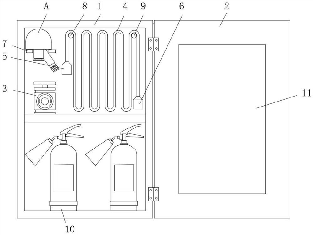
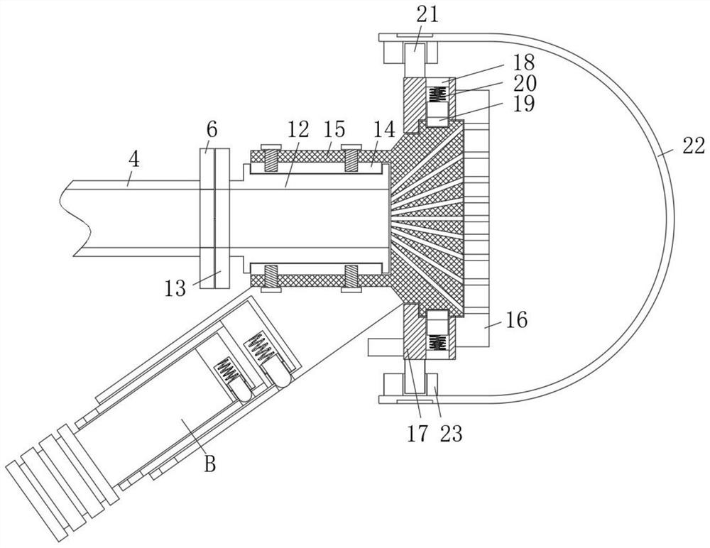
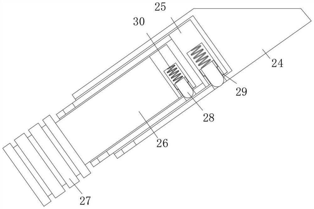
[0026] refer to Figure 1-4 A fire box convenient for rapid unwinding of pipelines comprises a cabinet body 1, wherein a fire hydrant 3, a fire hose 4 and a water outlet joint A are arranged in the cabinet body 1, and the water outlet joint A comprises an inner pipe 12, one end of which is provided with a clamping flange 3 13, the outer side of the inner pipe 12 is provided with a ring groove and is rotatably sleeved with a collar 14, the outer side of the ring body of the collar 14 is fixedly sleeved with a water dispersing base 15, and one end of the water dispersing base 15 has a frustum-shaped structure. The distributor base 15 is provided with a divergent water hole I which is communicated with the inner pipe 12. A quantitative ring 17 is rotatably sleeved on the outer side of the distributor base 15. One end of the quantitative ring 17 is fixedly connected with a distributor plate 16, which is located at one end of the distributor base 15, and the plate body of the distributo...

Embodiment 2

[0030] such as Figure 1-4 As shown, this embodiment is basically the same as Embodiment 1. Preferably, the inner wall of the cabinet body 1 is fixedly provided with a placing seat 7 for placing the water outlet connector A, and a round pin 1 8 and a round pin 2 9 for storing the fire hose 4.

[0031] In this embodiment, it is convenient to store and store the whole fire hose 4, and it is more convenient to take it out in subsequent use.

Embodiment 3

[0033] such as Figure 1-4 As shown, this embodiment is basically the same as Embodiment 1. Preferably, one end of the fire hose 4 is provided with a clamping flange 1 5 matched with the fire hydrant 3, and the other end of the fire hose 4 and one end of the inner pipe 12 are respectively provided with a clamping flange 2 6 and a clamping flange 3 13 matched with each other.

[0034] In this embodiment, the water outlet joint A is fixedly communicated with the fire hose 4 through the clamping flange 3 13 and the clamping flange 2 6.


PUM


Abstract

The fire box comprises a cabinet body, a fire hydrant, a fire hose and a water outlet connector are arranged in the cabinet body, the water outlet connector comprises an inner pipe, a third clamping flange is arranged at one end of the inner pipe, an annular groove is formed in the outer side of a pipe body of the inner pipe, and the outer side of the pipe body of the inner pipe is rotationally sleeved with a lantern ring; the outer side of a ring body of the lantern ring is fixedly sleeved with a water dispersing base, one end of the water dispersing base is of a circular-truncated-cone-shaped structure, the water dispersing base is provided with first water holes which are in a divergent mode and communicate with the inner pipe, the outer side of the water dispersing base is rotationally sleeved with a quantitative ring, one end of the quantitative ring is fixedly connected with a water dispersing plate, and the other end of the quantitative ring is fixedly connected with the water dispersing plate. The water dispersing plate is located at one end of the water dispersing base, and a plurality of sets of water passing channels are formed in a plate body of the water dispersing plate. The safety of the fire hose in the stretching process and the partition wall fire fighting process is improved, more labor is saved, use is convenient and fast, adjustment can be conducted in the water outlet process, and the use requirements of people in production and life are met.

Description

Technical field [0001] The invention relates to the technical field of fire fighting equipment, in particular to a fire box which is convenient for rapid unwinding of pipelines. technical background [0002] Fire hydrant box refers to the box used to store fire hydrants, which is used to extinguish fires when a fire breaks out. It needs to be equipped with hoses, water guns, etc. The installation methods are open-mounted, concealed-mounted and semi-concealed-mounted. In the actual use process of the existing fire box, people will open the fire hydrants at the same time when they disperse the hoses. The purpose is to flush the hoses through the impact of water, and the originally twisted hoses will also be dredged under the impact of water flow. However, in this process, People usually hold the connecting flange at one end of the hose. When the water quickly dredges the hose, it also makes the connecting flange rotate, which makes people unable to hold the connecting flange, causi...

Claims


Application Information

Patent Timeline
Patent Type & Authority Applications(China)
IPC IPC(8): A62C35/20A62C33/04
CPCA62C35/20A62C33/04
Inventor 徐祖银徐云峰徐传林
Owner 天长市鹏展消防设备制造有限公司
Learn More