Elbow machining device
A technology for processing devices and elbows, which is applied in the direction of storage devices, feeding devices, positioning devices, etc., can solve the problems of bend deviation, large tolerance, and difficulty in fitting into pipelines, etc., and achieve the effect of reducing tolerances and facilitating installation
- Summary
- Abstract
- Description
- Claims
- Application Information
AI Technical Summary
Problems solved by technology
Method used
Image

Examples
Embodiment 1
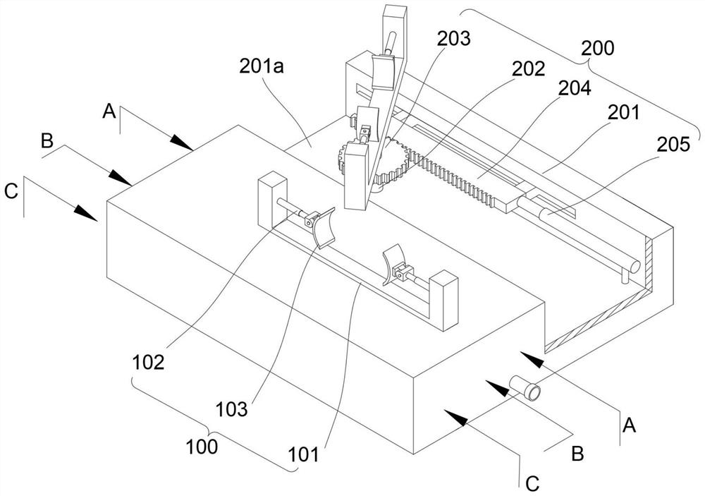
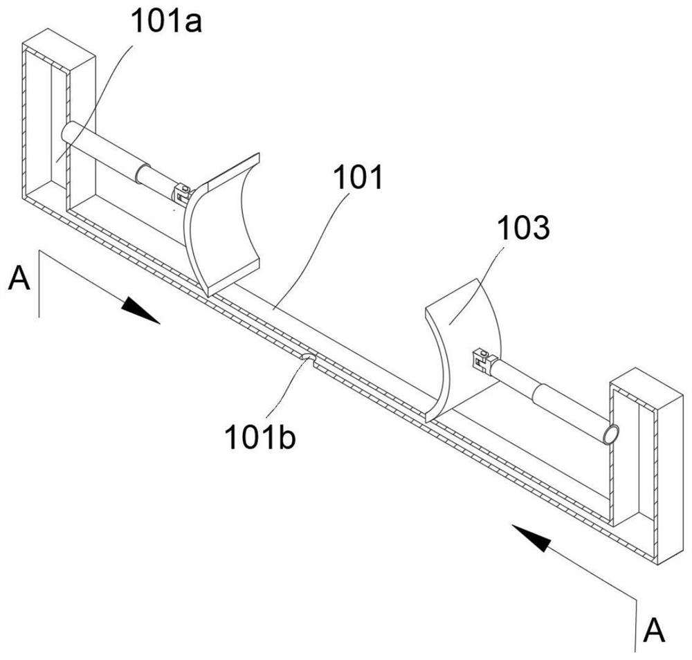
[0027] refer to figure 1 , which is the first embodiment of the present invention, this embodiment provides an elbow processing device, a clamping assembly 100 and an adjusting assembly 200, the clamping assembly 100 includes a base 101, a first telescopic rod 102 and a splint 103, the base 101 The first telescopic rod 102 is arranged symmetrically on the top, and the first telescopic rod 102 is connected to the splint 103; the two ends of the base 101 protrude upwards, and the first telescopic rod 102 is fixedly connected to the opposite sides of the two ends of the base 101, and the first telescopic rod 102 is opposite The splints 103 are respectively fixedly connected near the ends, and the inner wall of the splints 103 is arc-shaped, which is convenient for clamping and fixing the ends of the bent pipes.
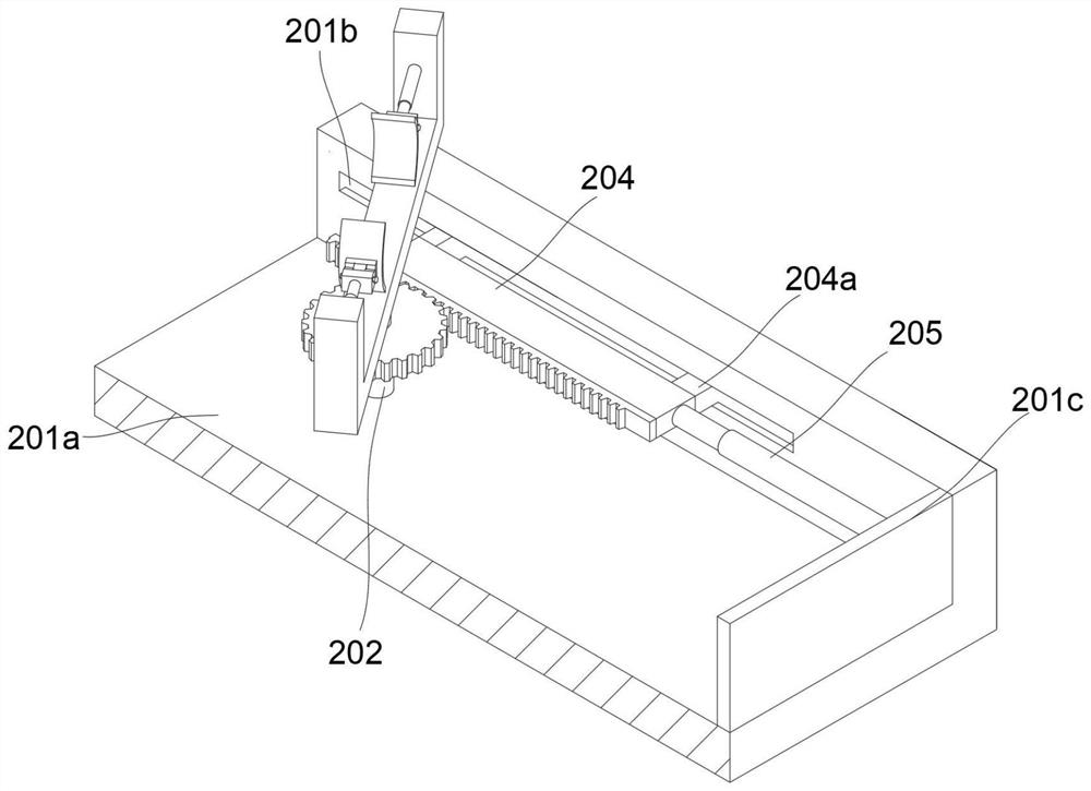
[0028] The adjustment assembly 200 includes a fixed seat 201, a rotating shaft 202, a gear 203, a tooth plate 204 and a second telescopic rod 205. The clamping assembly ...
Embodiment 2
[0030] refer to Figure 1~6 , which is the second embodiment of the present invention. This embodiment is based on the previous embodiment. A cavity 101a is provided inside the base 101. The cavity 101a is arranged inside the base 101 corresponding to the shape of the base 101. The cavity 101a passes through the first through hole 101b communicates with the outside world, the gas can enter the cavity 101a through the first through hole 101b, and the cavity 101a communicates with the inside of the first telescopic rod 102, the gas in the cavity 101a can enter the inside of the first telescopic rod 102, through the air pressure The change controls the expansion and contraction of the first telescopic rod 102 .
[0031] The fixed seat 201 is provided with a groove 201a, and the rotating shaft 202 is arranged to rotate in the groove 201a, and the inner wall of one side of the groove 201a is provided with a chute 201b, and the tooth plate 204 is provided with a slider 204a on the s...
Embodiment 3
[0039] refer to Figure 1 ~ Figure 3 , Figure 5 and Image 6 , is the third embodiment of the present invention. This embodiment is based on the above two embodiments. During use, the compressed gas is passed into the intake pipe 301a through the existing air pump, and the gas in the intake pipe 301a enters the control pipe 301, and the gas Pass through the vent hole 301c-5 on the second column 301c-3 and enter between the first column 301c-1 and the second column 301c-3, enter the tee head 302 through the second through hole 301d, and then pass through the connecting pipe 302a enter the sleeve 202b, and enter the first through hole 101b through the rotating shaft 202, enter the cavity 101a, and then enter the first telescopic rod 102. When the gas continues to pass through, the air pressure increases, which can push the first telescopic rod 102 to extend. Drive the splint 103 to clamp one end of the elbow; the gas in the tee 302 enters the first through hole 101b on the ot...
PUM
 Abstract
Description
Claims
Application Information
 - R&D
- Intellectual Property
- Life Sciences
- Materials
- Tech Scout
- Unparalleled Data Quality
- Higher Quality Content
- 60% Fewer Hallucinations
Browse by: Latest US Patents, China's latest patents, Technical Efficacy Thesaurus, Application Domain, Technology Topic, Popular Technical Reports.
© 2025 PatSnap. All rights reserved.Legal|Privacy policy|Modern Slavery Act Transparency Statement|Sitemap|About US| Contact US: help@patsnap.com