
Gear broaching clamp for steering gear rack

A steering gear and fixture technology, which is applied to components with teeth, gear tooth manufacturing devices, gear teeth, etc., can solve problems such as poor finish, steering gear rack tooth top drum shape parameters that cannot meet the requirements, and low efficiency. , to achieve the effect of ensuring consistency

Pending Publication Date: 2022-05-10
EST TOOLS
View PDF7 Cites 0 Cited by
  • Summary
  • Abstract
  • Description
  • Claims
  • Application Information

AI Technical Summary

Problems solved by technology

[0003] The existing steering gear rack processing often adopts the method of milling teeth, which has the problems of low efficiency and poor finish, and the tooth tip crowning parameters of the processed steering gear rack cannot meet the requirements

Method used


Image

  • Gear broaching clamp for steering gear rack
  • Gear broaching clamp for steering gear rack
  • Gear broaching clamp for steering gear rack

Examples


Embodiment Construction

[0036] In order to make the object, technical solution and advantages of the present invention clearer, the present invention will be further described in detail below in conjunction with the accompanying drawings and embodiments. It should be understood that the specific embodiments described here are only used to explain the present invention, not to limit the present invention.

[0037] On the contrary, the present invention covers any alternatives, modifications, equivalent methods and schemes within the spirit and scope of the present invention as defined by the claims. Further, in order to make the public have a better understanding of the present invention, some specific details are described in detail in the detailed description of the present invention below. The present invention can be fully understood by those skilled in the art without the description of these detailed parts.

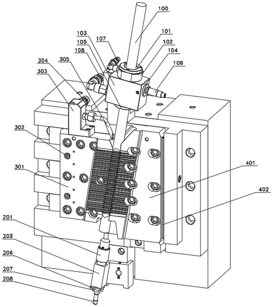
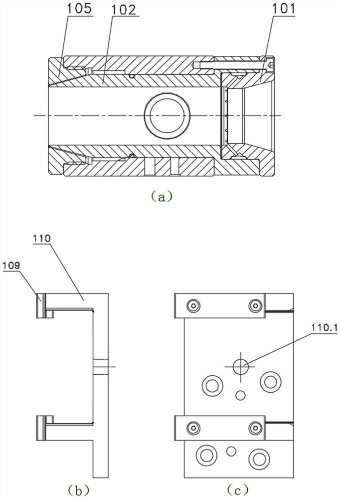
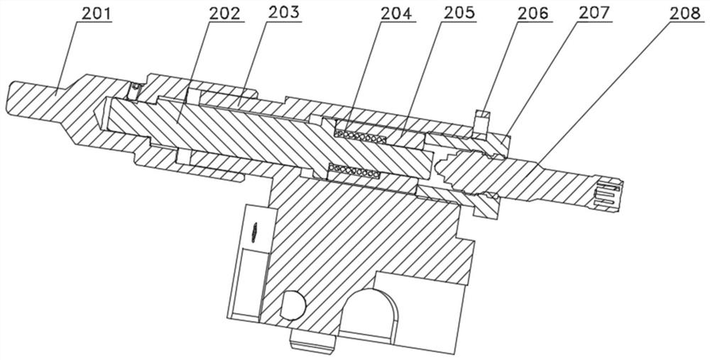
[0038] Such as Figure 1-5 As shown, a pull-tooth clamp for a steering gear rack acco...


PUM


Abstract

The invention belongs to the technical field of mechanical equipment, and particularly relates to a gear broaching clamp for a steering gear rack, which comprises an upper leading-in device, a lower positioning device, a jaw 1 device and a jaw 2 device, the upper guiding-in device is located at the upper end of the gear broaching clamp and comprises a clamping module, a detecting module and a flushing module. A vertically-through cylindrical pipeline is arranged in the clamping module and used for allowing a workpiece to pass through and clamping the workpiece. The detection module is used for detecting whether a workpiece enters the upper guide-in module or not; the flushing module is used for externally connecting an oil way and flushing a workpiece; the lower positioning device is located at the lower end of the gear broaching clamp and used for detecting the axial position of the workpiece. The first jaw device and the second jaw device are located between the upper guiding-in device and the lower positioning device, arranged on the left side and the right side correspondingly and used for being matched with each other to clamp a workpiece. The sensor can play a role in mistake proofing, damage to a mechanical structure is avoided, and the consistency of repeated positioning is guaranteed; the oil pipe can prevent the surface of the workpiece from generating pits and even causing size out-of-tolerance.

Description

technical field [0001] The invention belongs to the technical field of mechanical equipment, and in particular relates to a pull-tooth clamp for a steering gear rack. Background technique [0002] The rack and pinion steering gear is based on the gear and rack transmission as the transmission mechanism, and is often used in the steering system of automobiles. Among them, the steering gear rack requires high meshing precision. Therefore, in batch processing, the requirements for dimensional accuracy, surface roughness and dimensional consistency are high. [0003] The existing steering gear racks are usually processed by tooth milling, which has the problems of low efficiency and poor finish, and the tooth tip crowning parameters of the processed steering gear racks cannot meet the requirements. Contents of the invention [0004] In order to solve the above problems, the present invention provides a pull-tooth clamp for a steering gear rack with high positioning accuracy ...

Claims


Application Information

Patent Timeline
Patent Type & Authority Applications(China)
IPC IPC(8): B23F23/06B23F23/00B23Q17/00
CPCB23F23/06B23F23/00B23Q17/002
Inventor 许尖陈子彦董兢超潘明锋张云凯龚凌浩
Owner EST TOOLS
Learn More