Ground suction nozzle of electric sweeping appts.

A cleaning and ground technology, applied in the direction of suction nozzles, vacuum cleaners, suction hoses, etc., can solve the problems such as the inability to move the ground suction nozzles at will, difficult operation of the ground suction nozzles, and the inability of the ground suction nozzles to move.

Inactive Publication Date: 2004-04-07
MITSUBISHI ELECTRIC CORP +1
View PDF1 Cites 0 Cited by
  • Summary
  • Abstract
  • Description
  • Claims
  • Application Information

AI Technical Summary

Problems solved by technology

[0015] The left and right ends of the lower housing 2 are provided with spherical casters 21 that can freely rotate 360 ​​degrees, and feathers 22 are provided before and after the suction port 8, and slits are provided at multiple positions of one group (front group) of feathers 22 23, there is such a problem: as in the above-mentioned first prior art example, the feathers 22 of another group (rear group) will function as shielding bodies, and not only cannot absorb the dust, and because the straightness of the spherical casters 21 is poor, it is difficult to operate the floor suction nozzle, and the floor suction nozzle cannot be moved freely, and the arm will feel very strenuous if it is moved forcibly
[0016] In addition, for the common suction nozzles fixed with felt or planted with wool, there are also problems such as the operation on the carpet becomes very heavy, and even the suction nozzle on the floor cannot move.

Method used


Image

  • Ground suction nozzle of electric sweeping appts.
  • Ground suction nozzle of electric sweeping appts.
  • Ground suction nozzle of electric sweeping appts.

Examples


Embodiment Construction

[0060] Embodiment of the invention

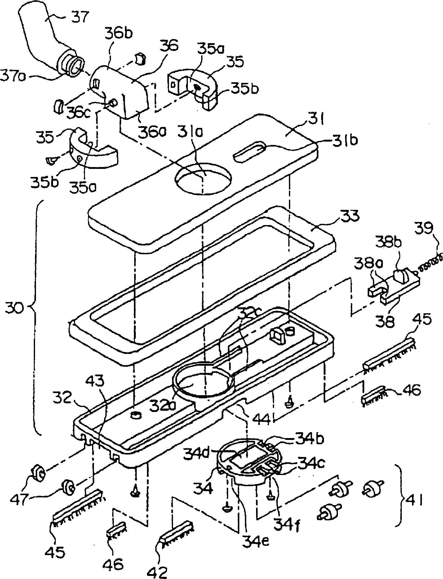
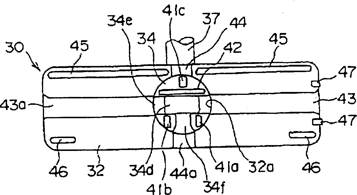
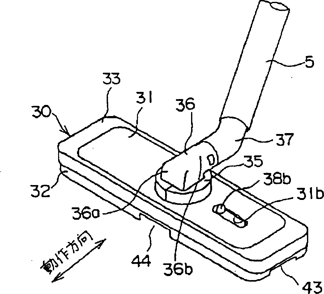
[0061] In each figure, reference numeral 31 is a substantially rectangular upper case, and reference numeral 32 is a similarly substantially rectangular lower case, which are joined together via a shock absorber 33 formed of a soft material, and the upper and lower cases 31, 32 And the shock absorber 33 constitutes the nozzle main body 30 . Reference numeral 34 is a rotating plate that is inserted from below into the holes 31a, 32a provided at approximately the center of the upper and lower housings 31, 32 and installed so as to be horizontally rotatable relative to the nozzle main body 30. By making the flange 34a such as Figure 9 As shown in contact with the stepped portion 32b of the lower housing 32, the depth of insertion from below can be defined. Reference numeral 35 is inserted into the holes 31a, 32a of the upper and lower housings 31, 32 from above so as to be integrated with the rotating plate 34, and is composed of two parts d...


PUM


Abstract

The invention provides a floor suction nozzle of an electric sweeper. By adopting the invention, not only ordinary floor but also narrow positions can be cleaned without replacing the suction nozzle. In addition, although a brush body is adopted for operation, the invention is very light. The connecting part between the main body 30 of the suction nozzle and an elbow 37 is provided with wheels 41a, 41b and 41c, wind paths 34e and 34f, and a swivel plate 34. The main body 30 of the suction nozzle consists of an oblong upper shell 31 and an oblong lower shell 32; the swivel plate 34 is linked with the elbow 37 which rotates horizontally, and is accordingly rotated.

Description

technical field [0001] The invention relates to a floor suction nozzle of a general household electric sweeper. Background technique [0002] Figure 16 to Figure 2 0 shows the first existing example of the suction nozzle for the floor of the existing electric cleaner as disclosed in JP-A-61-240929, Figure 16 for its stereogram, Figure 17 It is a bottom view, and Fig. 18 is a side view of the state when cleaning the carpet with the floor suction nozzle, Figure 19 It is a side view of the state when the floor suction nozzle is used to clean the floor, and Fig. 20 is a situation where the user uses the suction nozzle to clean. [0003] Figure 16 to Figure 2 In 0, the number 1 is a roughly rectangular upper case, and the number 2 is the same lower case, which are connected by a shock absorber 3 formed of soft material, and the upper and lower cases 1, 2 and the shock absorber 3 constitute Suction nozzle main body 15. Reference numeral 4 is an elbow substantially bent in...

Claims


Application Information

Patent Timeline
Patent Type & Authority Patents(China)
IPC IPC(8): A47L9/00A47L5/36A47L9/02A47L9/06A47L9/24
CPCA47L9/02A47L9/0606
Inventor 乳井一夫莲浩二石井史郎上冈孝畅石田则之
Owner MITSUBISHI ELECTRIC CORP
Why Eureka
Try Eureka