High-intensity earthquake area airport GTC high-speed rail elevated station bridge and construction method thereof

A technology for earthquake zones and bridges, applied in bridges, stations, bridge parts, etc., can solve the problems of complex construction, many interface designs, and tight construction period, and achieve the effect of shortening construction period, avoiding mutual interference, and shortening construction period.

Pending Publication Date: 2022-05-10
KUNMING SURVEY DESIGN & RES INST OF CREEC
View PDF8 Cites 0 Cited by
  • Summary
  • Abstract
  • Description
  • Claims
  • Application Information

AI Technical Summary

Problems solved by technology

Conventional high-speed rail station bridges are generally independent station bridges or bridge-building integrated structures, while high-speed rail station bridges located in GTC are intertwined with airport buildings and subways, with many interface designs and great mutual influence. The vibration is large, and it will cause vibration problems when it is close to the building structure; the high-speed rail platform bridge is connected with the airport building, and there is a fire protection problem that needs to be dealt with according to the airport regulations, and the escalator passage is considered on the platform beam; there is a consideration for the overall aesthetics of the airport, which needs to be There are problems such as the use of column-free canopies; there are problems such as complex construction and tight construction period

Method used


Image

  • High-intensity earthquake area airport GTC high-speed rail elevated station bridge and construction method thereof
  • High-intensity earthquake area airport GTC high-speed rail elevated station bridge and construction method thereof
  • High-intensity earthquake area airport GTC high-speed rail elevated station bridge and construction method thereof

Examples


Embodiment 1

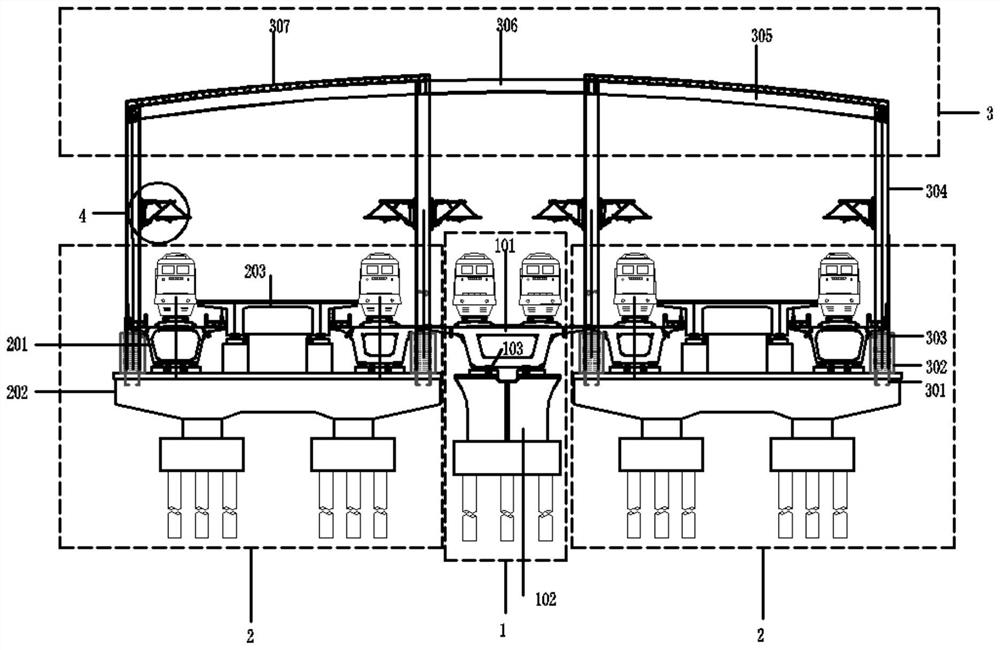
[0035] Such as Figure 1-6 As shown, the high-intensity earthquake area airport GTC high-speed rail elevated station bridge consists of four parts, namely the main line bridge 1, the arrival and departure line bridge 2, the column-free metal canopy 3 and the catenary 4.

[0036] In this embodiment, there are two 6-line station bridges. The arrival-departure bridge 2 travels at a slower speed, and the main-line bridge 1 travels at a faster speed. The main-line bridge 1 and the arrival-departure bridge 2 are separated, and the gap between the two bridges is not less than 5cm . The driving speed of the bridge 1 on the main line is high, and the vibration effect generated is great. The separation type can prevent the vibration of the bridge 1 on the main line from affecting other buildings.

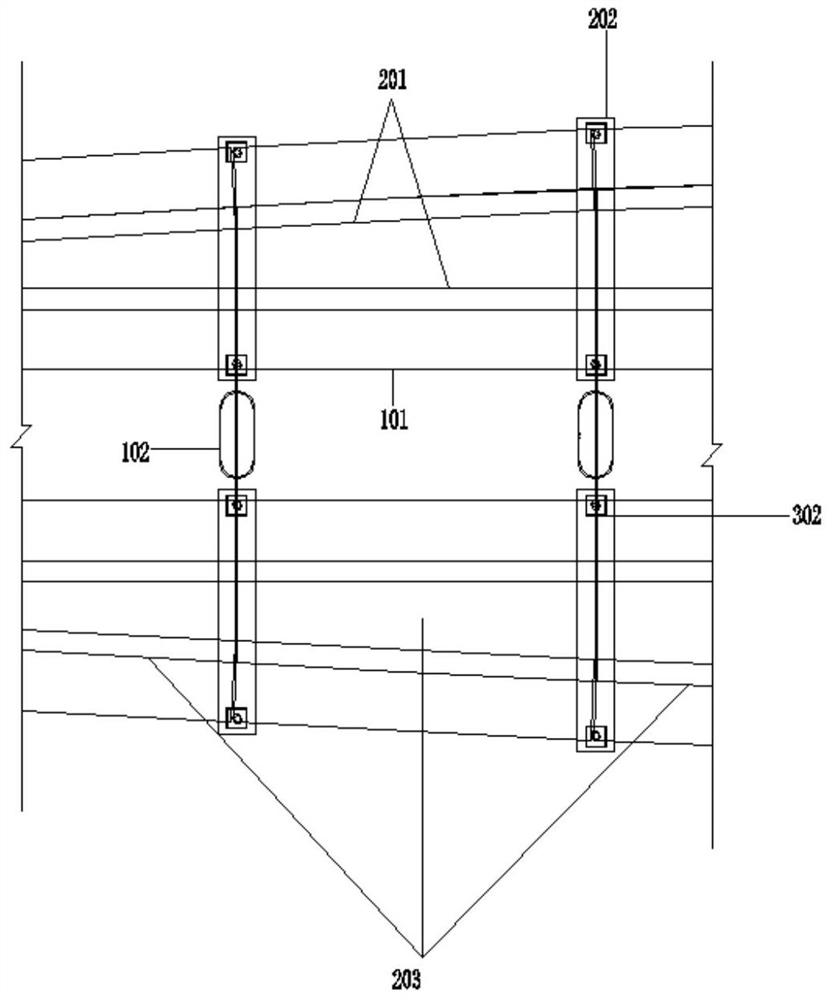
[0037] The common section steel anti-fall beam 103 on the main line is pre-embedded at the bottom of the corresponding main line box girder 101, and the ordinary section steel anti-fall beam...


PUM


Abstract

The invention relates to a high-intensity earthquake area airport GTC high-speed rail elevated station bridge and a construction method thereof, and belongs to the technical field of rail transit bridges, the high-intensity earthquake area airport GTC high-speed rail elevated station bridge comprises a high-speed rail elevated station bridge composed of a main track bridge, an arrival-departure track bridge, a non-column metal canopy, a platform beam and a contact network, and the main track bridge and the arrival-departure track bridge are separated. The lower part of the main track bridge adopts a round-end pier, and the foundation adopts a pile group foundation; pi-shaped piers are adopted for arrival-departure line bridges, and pile group foundations are adopted for foundations; the column-free metal canopy, the arrival-departure line box girder and the platform girder are arranged on the arrival-departure line pi-shaped pier; the contact net is welded on a stand column of the column-free metal canopy; the anti-seismic performance is good, in the construction process, the construction sequence problem of the canopy foundation and the bridge is solved, and the construction period is shortened. Compared with a traditional bridge platform bridge, the functions are more complete and reasonable; compared with a traditional bridge building integrated platform, the engineering scale is reduced.

Description

technical field [0001] The invention belongs to the technical field of rail transit bridges, and in particular relates to an elevated station bridge of an airport GTC high-speed railway in a high-intensity earthquake area. Background technique [0002] The existing airport expansion project introduces more and more high-speed railways to form a regional comprehensive transportation hub (GTC) where aviation, highways, railways, underground rails and other systems converge and radiate in all directions, so as to achieve the goal of "zero transfer". Conventional high-speed rail station bridges are generally independent station bridges or bridge-building integrated structures, while high-speed rail station bridges located in GTC are intertwined with airport buildings and subways, with many interface designs and great mutual influence. The vibration is large, and it will cause vibration problems when it is close to the building structure; the high-speed rail platform bridge is co...

Claims


Application Information

Patent Timeline
Patent Type & Authority Applications(China)
IPC IPC(8): E04H3/00E01D2/04E01D19/02B61B1/00
CPCE04H3/00E01D2/04E01D19/02B61B1/00
Inventor 李冲杰户东阳李聪林陈克坚卢三平郭晓玉吕雷周昆罗谦刚陈德绍林杉苏波胡志林陈玉峰曾湘衡杨业新史棚飞
Owner KUNMING SURVEY DESIGN & RES INST OF CREEC
Why Eureka
Try Eureka