Check patentability & draft patents in minutes with Patsnap Eureka AI!

Ultra-precision cutting tool state parameter calculation method and system and application

A technology of state parameters and cutting processing, applied in the field of cutting processing, can solve problems such as inability to flexibly use multiple processing modes, lack of intuition, and too abstract derivation process, to achieve accuracy guarantee, clear geometric relationship, and strong applicability Effect

Active Publication Date: 2022-05-10
TIANJIN UNIV
View PDF6 Cites 0 Cited by
  • Summary
  • Abstract
  • Description
  • Claims
  • Application Information

AI Technical Summary

Problems solved by technology

[0004] The existing methods for calculating the attitude field parameters of ultra-precision cutting tools mainly use geometric relations for pure mathematical derivation, which cannot be flexibly applied to the analysis of various processing modes, and the derivation process is too abstract and lacks intuition

Method used


Image

  • Ultra-precision cutting tool state parameter calculation method and system and application
  • Ultra-precision cutting tool state parameter calculation method and system and application
  • Ultra-precision cutting tool state parameter calculation method and system and application

Examples


Embodiment 1

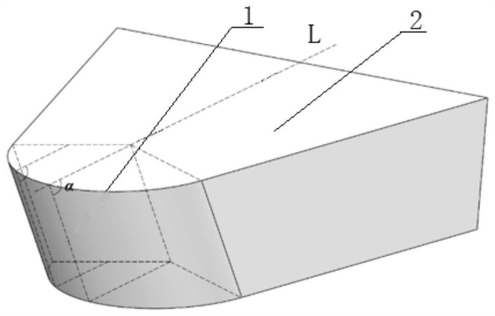
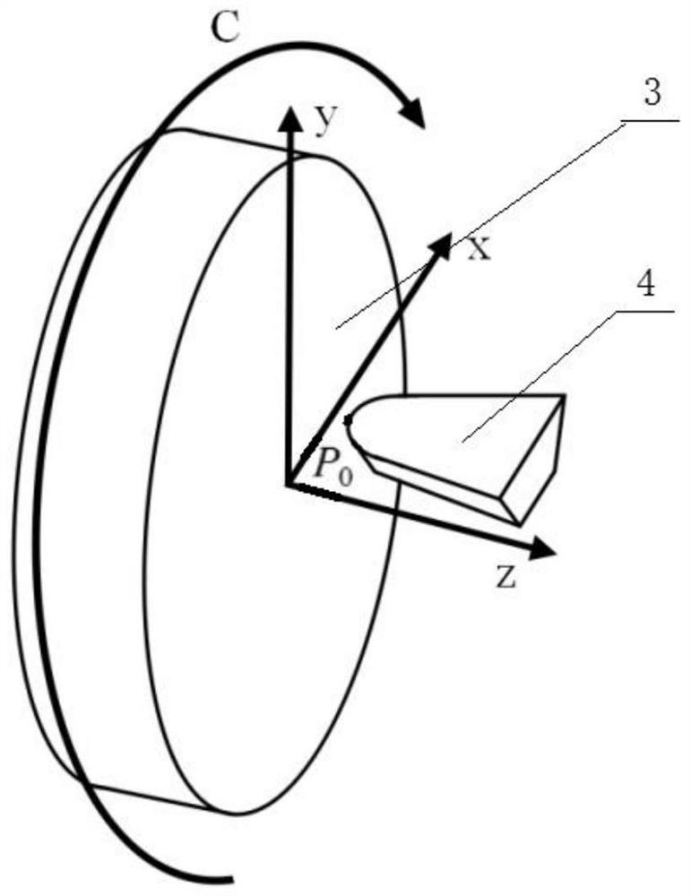
[0075] This embodiment of the invention provides a method for calculating the state parameters of ultra-precision cutting tools, which is used for example. Figure 1 The attitude field analysis of the inclined cylindrical diamond tool 4 shown in. such as Figure 2 As shown, in the machining process, the machined surface 3 rotates in the C direction around the main axis of rotation, and the cutter feeds along the X axis and the Z axis.

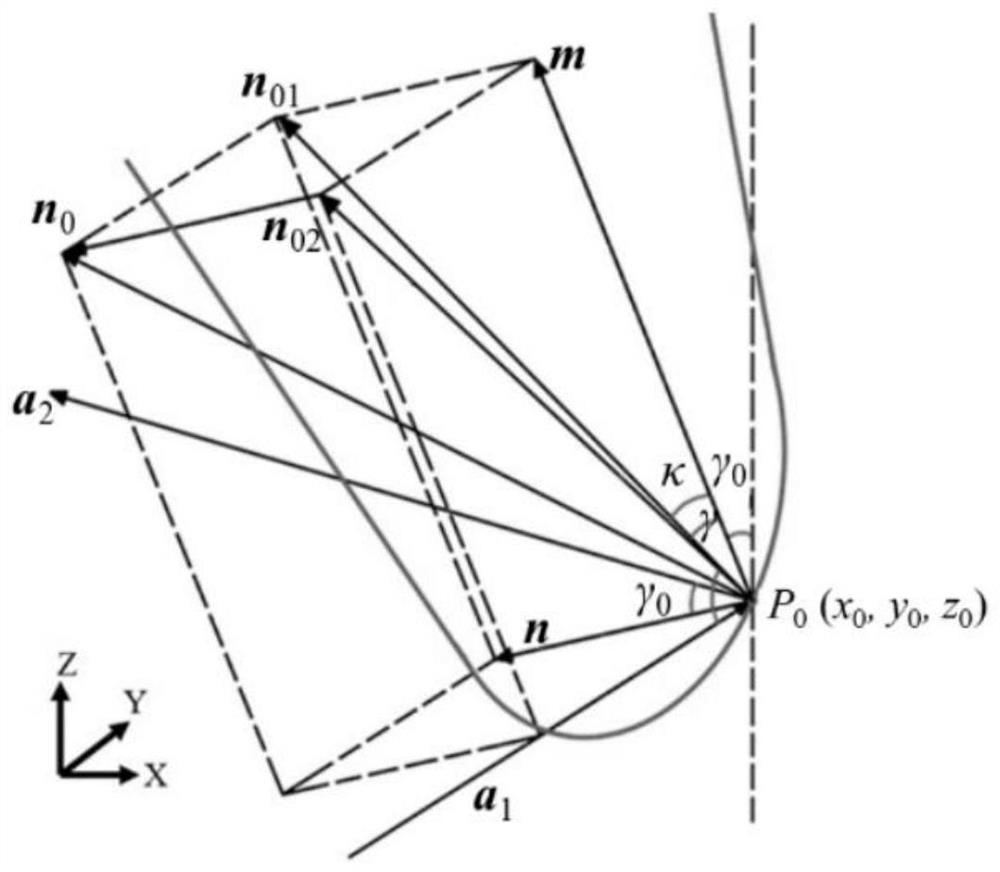
[0076] It should be noted that before cutting, in order to prevent the cutter 4 from breaking, it is necessary to adjust the angle of the cutter 4 in advance, and adjust the cutter 4 to the initial posture, which will always be maintained during cutting. If the central axis of the rake face 2 of the cutter 4 before adjustment is L, and L is parallel to the Z axis, then the initial rake angle γ. 0 Is the angle between the rake face 2 and L of the adjusted tool 4 in the initial state, that is, the angle between the central axis of the rake face of the ...

Embodiment 2

[0101] The invention provides a method for calculating the state parameters of cutting tools in ultra-precision cutting. The processing method of rotary cutting is as follows Figure 4 、 5 As shown, in the actual machining process, the cutter is fixed, the machined surface 6 rotates around the center of rotation, and at the same time, it is linked in the Y-axis and Z-axis directions. The cutting trajectory of the cutter on the machined surface 6 is projected as shown in Figure 6. Figure 5 On the cylindrical structure 5 shown, it is distributed in a thread shape along the circumferential direction. In the analysis process, it can be seen that the tool moves in the cylindrical structure 5, and its rotation center is located in the cylindrical structure 5, and its rotation direction can be seen as Figure 4 Move in direction D as shown. When the cutter moves counterclockwise along the thread track, the initial rake angle γ is set when the cutter leans forward. 0 Take negative value.

...

Embodiment 3

[0125] The invention provides a method for calculating the state parameters of cutting tools in ultra-precision cutting. The grid line planing method is as follows Figure 7 、 8 As shown in the figure, in the actual machining process, the cutter is kept fixed, and the machined surface moves relative to the cutter for cutting. The moving mode of the machined surface 6 is as follows: the cutter cuts a curved track on the machined surface 6 along the Y-axis and Z-axis, then the machined surface 6 returns to its initial position, rotates in the E-direction around the central axis of rotation, fine-tunes the machining angle, and then moves along the Y-axis and Z-axis. The above steps are repeated until the machining is completed, and the cutting path of the cutter relative to the machined surface 6 is grid-line. Projecting the running track of the tool on the curved surface onto the cylindrical structure 5 to obtain the following results. Figure 8 In the analysis process, the tool can b...


PUM


Abstract

The invention discloses a method for calculating state parameters of an ultra-precision cutting tool, which comprises the following steps of: 1, constructing a tool attitude field cube model, and establishing the tool attitude field cube model by taking a tool attitude as a reference, a side face A in the cutter attitude field cube model is a plane which passes through the central axis of the rake face and is perpendicular to the rake face, a side face B of the cutter attitude field cube model is a plane which coincides with the rake face, and the side face A is adjacent to the side face B; 2, establishing a Cartesian coordinate system; and step 3, calculating cutter state parameters. According to the method, the cutter attitude field cube model is established, the vectors needed in the cutter attitude field parameter calculation process are put into the cube, the relation between the cutter attitude field parameters to be calculated and the influence of the relative position relation between the cutter and the curved surface on different parameter sizes can be visually seen, the geometrical relation between the vectors is clear, and the calculation accuracy is high. And a calculation formula of the cutter attitude field parameters can be quickly and intuitively deduced.

Description

Technical field [0001] The invention belong to that field of cutting proces, in particular to a method, a system and an application for calculating state parameters of ultra-precision cutting tool. technical background [0002] Ultra-precision cutting is an important manufacturing technology of optical free-form surface, which can obtain sub-micron surface accuracy and nano-scale surface quality. In the process of machining, we need to achieve higher machining accuracy. In this process, besides the manufacturing and assembly accuracy of hardware equipment such as spindle system, we also need to pay attention to the contact state between cutter and workpiece surface, because this is also an important factor affecting its machining effect. This requires the analysis of ultra-precision cutting methods, the understanding of the processed optical free-form surface, the use of geometric and mathematical methods to judge the spatial interference between the tool and the workpiece during...

Claims


Application Information

Patent Timeline
Patent Type & Authority Applications(China)
IPC IPC(8): G06T7/70G06T7/00G06T17/10
CPCG06T7/70G06T7/0004G06T17/10G06T2207/30108Y02P90/02
Inventor 李泽骁张效栋纪俊棋
Owner TIANJIN UNIV
Features
  • R&D
  • Intellectual Property
  • Life Sciences
  • Materials
  • Tech Scout
  • Unparalleled Data Quality
  • Higher Quality Content
  • 60% Fewer Hallucinations
Learn More