
Flat wire continuous wave winding structure, stator with same, motor and vehicle

A wave winding and winding technology, which is applied in flat wire continuous wave winding structures, stators, motors and vehicles, can solve the problems of increasing the additional loss of motors, difficulty in arranging wave windings, and high mold investment costs, so as to improve slot fill rate, The effect of increasing the available space and improving performance

Pending Publication Date: 2022-05-10
ZHUZHOU CSR TIMES ELECTRIC CO LTD
View PDF0 Cites 0 Cited by
  • Summary
  • Abstract
  • Description
  • Claims
  • Application Information

AI Technical Summary

Problems solved by technology

[0005] 1) There is a problem of asymmetry in the winding branch, which will lead to differences in back EMF, resistance, inductance, etc., resulting in a decrease in motor performance, resulting in winding circulation, increasing the additional loss of the motor, and causing local overheating of the motor
[0006] 2) The arrangement of the wave winding is difficult, it is easy to overlap, and it is difficult to insert it into the stator slot
[0007] 3) When the wave winding span is different, the manufacturing process is complicated, the mold investment cost is high, and the production is difficult

Method used


Image

  • Flat wire continuous wave winding structure, stator with same, motor and vehicle
  • Flat wire continuous wave winding structure, stator with same, motor and vehicle
  • Flat wire continuous wave winding structure, stator with same, motor and vehicle

Examples


Embodiment 1

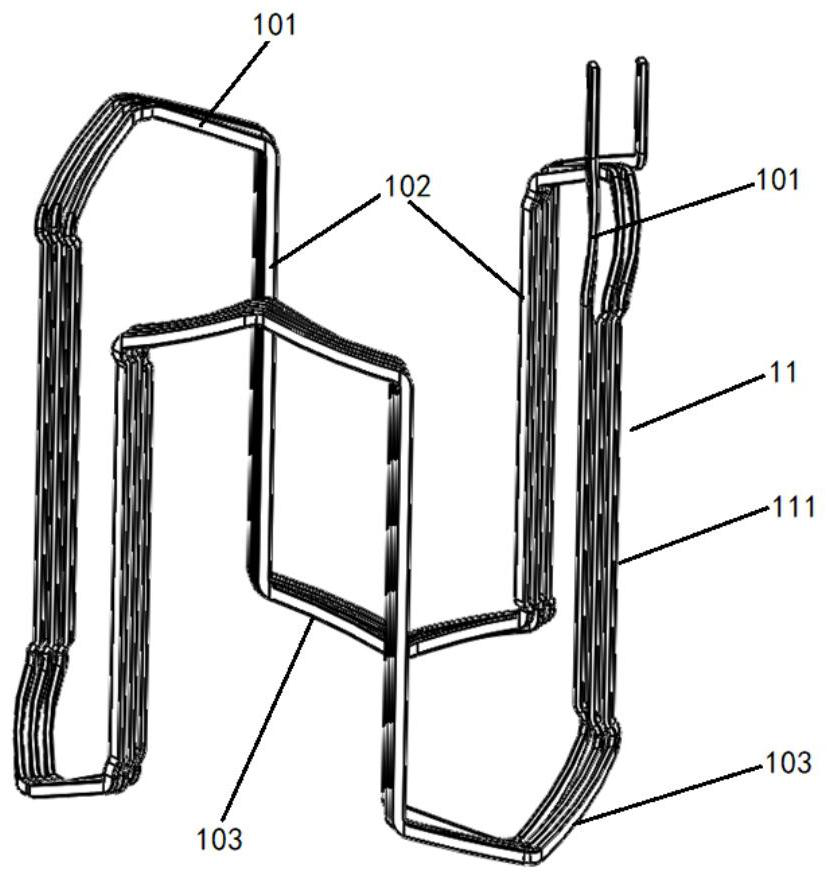
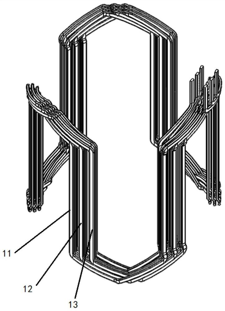
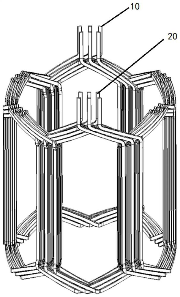
[0057] The flat wire continuous wave winding structure of the present invention includes a three-phase continuous wave winding, and each phase continuous wave winding includes an incoming wire end, an outgoing wire end and a continuous wave winding coil located between the incoming wire end and the outgoing wire end. It can be understood that the flat wire continuous wave winding structure in this embodiment may be in the form of U, V, W three-phase windings.

[0058] The continuous wave winding of each phase includes the first branch winding and the second branch winding in parallel, the number of stator slots of each phase branch winding is nm, the total number of stator slots is 3nm, n is the number of poles of the motor, m is the number of coils contained in each branch winding; the number of winding layers of the stator slot is 2M layers, and the span of the coils in each layer is 3m; the incoming and outgoing ends of each phase continuous wave winding are located at The ...

Embodiment 2

[0084] The flat wire continuous wave winding structure of the present invention includes a three-phase continuous wave winding, and each phase continuous wave winding includes an incoming wire end, an outgoing wire end and a continuous wave winding coil located between the incoming wire end and the outgoing wire end. It can be understood that the flat wire continuous wave winding structure in this embodiment may be in the form of U, V, W three-phase windings.

[0085] The continuous wave winding of each phase includes the first branch winding and the second branch winding in parallel, the number of stator slots of each phase branch winding is nm, the total number of stator slots is 3nm, n is the number of poles of the motor, m is the number of coils contained in each branch winding; the number of winding layers of the stator slot is 2M layers, and the span of the coils in each layer is 3m; the incoming and outgoing ends of each phase continuous wave winding are located at The ...


PUM


Abstract

The invention discloses a continuous wave winding structure which comprises three phases of continuous wave windings, and each phase of continuous wave winding comprises a wire inlet end, a wire outlet end and a continuous wave winding coil located between the wire inlet end and the wire outlet end. Each phase of continuous wave winding comprises a first branch winding and a second branch winding which are connected in parallel, the number of stator slots of each phase of branch winding winding is nm, the total number of the stator slots is 3nm, n is the number of poles of the motor, and m is the number of coils included in each branch winding; the number of winding layers of the stator slot is 2M, and the span of the coil in each layer is 3m; the wire inlet end and the wire outlet end of each phase of continuous wave winding are located at the groove bottom or the groove opening of the stator groove; n, m and M are all positive integers. The transformer has the advantages of being compact in structure, balanced in potential of each branch, free of circulating current and the like, by adopting the winding arrangement mode that the same span and a plurality of coils are combined, overlapping is reduced, arrangement is neat, the complexity of the manufacturing process is reduced, and a series of problems caused by asymmetry of each branch can be eliminated.

Description

technical field [0001] The invention belongs to the technical field of motors, and in particular relates to a flat wire continuous wave winding structure, a stator having the same, a motor and a vehicle. Background technique [0002] With the rapid development of new energy vehicle technology, the drive motor, as one of the key executive components of electric vehicles, has higher and higher performance requirements. At present, high speed, light weight, and high efficiency have become the development trend of drive motors, and there are higher requirements for the power density, high efficiency area, and heat dissipation capacity of the motor. [0003] Stator windings can be divided into round wires and flat wires. Compared with round wire windings, flat wire windings can effectively increase the motor slot fill rate, reduce motor copper consumption and improve motor efficiency, and at the same time reduce the height of the motor winding ends. Thereby reducing the volume o...

Claims


Application Information

Patent Timeline
Patent Type & Authority Applications(China)
IPC IPC(8): H02K3/12H02K3/28H02K3/48
CPCH02K3/12H02K3/28H02K3/48
Inventor 陈致初史俊旭胡勇峰胡明罗晓祎江昕郑钦石鸿佼吴辉忠杨轶
Owner ZHUZHOU CSR TIMES ELECTRIC CO LTD
Learn More