Cardio-pulmonary resuscitation pressing device for emergency severe illness

A cardiopulmonary resuscitation and severe disease technology, applied in application, diagnosis, cardiac stimulation, etc., can solve problems such as inability to place a hospital bed, inability to adapt to the treatment of severe patients, large volume and difficult to carry, etc., and achieve a good limit and fixation effect

Pending Publication Date: 2022-05-13
GENERAL HOSPITAL OF NUCLEAR IND
View PDF7 Cites 1 Cited by
  • Summary
  • Abstract
  • Description
  • Claims
  • Application Information

AI Technical Summary

Problems solved by technology

[0003] The purpose of the present invention is to provide a cardiopulmonary resuscitation compression device for emergency critical care to solve the problem that the traditional cardiopulmonary resuscitation device proposed in the above background technology cannot be placed on the side of the hospital bed because of its large volume and is not suitable for the transfer process of critically ill patients. problems in treatment

Method used


Image

  • Cardio-pulmonary resuscitation pressing device for emergency severe illness
  • Cardio-pulmonary resuscitation pressing device for emergency severe illness
  • Cardio-pulmonary resuscitation pressing device for emergency severe illness

Examples


Embodiment 1

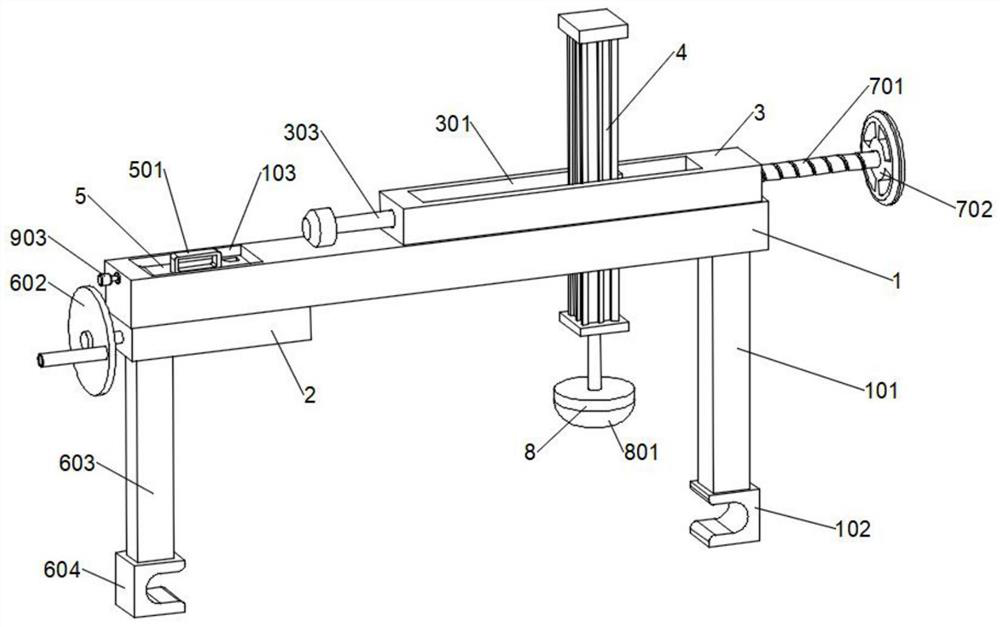
[0034] refer to Figure 1-6A cardiopulmonary resuscitation compression device for emergency severe cases is shown, including a horizontal frame 1, a bottom block 2, a top block 3, a servo electric cylinder 4 and a rechargeable battery 5, and a support is fixedly installed on the right side of the lower surface of the horizontal frame 1 Frame 101, the surface of the lower end of the support frame 101 is fixedly installed with an arc-shaped mouth clamping block A102, the bottom block 2 is fixedly installed on the left side of the lower surface of the horizontal frame 1, and a clamping assembly is arranged inside the horizontal frame 1, and the top block 3 is fixed Installed on the right side of the upper surface of the horizontal frame 1, the servo electric cylinder 4 is arranged vertically inside the installation top block 3 and penetrates to the bottom of the horizontal frame 1, the right end of the installation top block 3 is provided with an adjustment assembly, the horizonta...

Embodiment 2

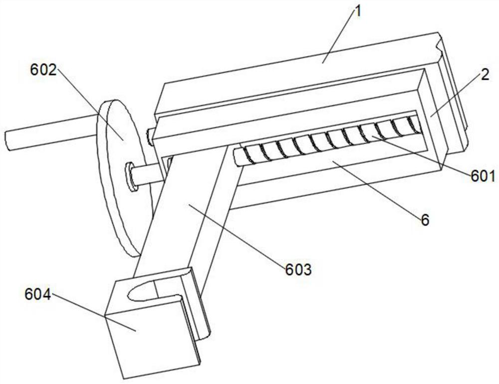
[0037] combine figure 1 with figure 2 As shown, based on the above-mentioned embodiment 1, the clamping assembly includes a limit groove 6 opened on the lower surface of the installation bottom block 2, and a threaded rod A601 is installed in the limit groove 6 for lateral rotation, and the left end of the threaded rod A601 extends through To the outside of the installation bottom block 2, the end of the threaded rod A601 located outside the installation bottom block 2 is fixed with a rocking plate 602, and the inside of the threaded rod A601 is slidably installed with a clamping rod 603 extending to the bottom of the installation bottom block 2, and the clamping rod 603 is correspondingly engaged and sleeved on the outside of the threaded rod A601, and the lower end of the clamping rod 603 is fixedly equipped with an arc-shaped clamping block B604. By rotating the rocking plate 602, the threaded rod A601 can be driven to rotate inside the limiting groove 6, combined with the...

Embodiment 3

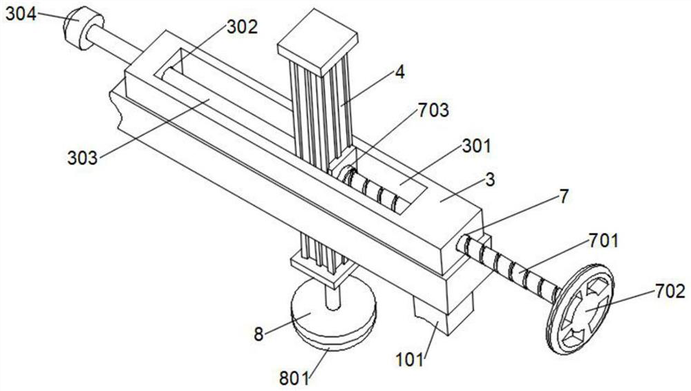
[0039] combine figure 1 with image 3 As shown, based on the above-mentioned embodiment 1 or 2, the upper surface of the installation top block 3 is provided with an installation through groove 301, and the installation through groove 301 penetrates to the bottom of the horizontal frame 1, and the servo electric cylinder 4 is slidably installed inside the installation through groove 301, The surface of the inner wall on the left side of the installation channel 301 is provided with a limit hole 302 that penetrates to the outside of the left side of the top block 3. The limit hole 302 is slidably installed with a limit rod 303, and the inner end of the limit rod 303 is fixedly connected to the servo motor. On the side surface of the cylinder 4, an end cap 304 is fixed on the outer end of the limit rod 303. When the servo electric cylinder 4 slides left and right inside the installation through groove 301, under the sliding cooperation between the limit rod 303 and the limit hol...


PUM


Abstract

The invention relates to the technical field of medical auxiliary devices, in particular to a cardio-pulmonary resuscitation pressing device for emergency severe illness, which comprises a transverse frame, a mounting bottom block, a mounting top block, a servo electric cylinder and a rechargeable storage battery, a supporting frame is fixedly mounted on the right side of the lower surface of the transverse frame, and an arc-shaped opening clamping block A is fixedly mounted on the surface of the lower end part of the supporting frame; the mounting bottom block is fixedly mounted on the left side of the lower surface of the transverse frame. A threaded rod A is driven to rotate through a rocking disc, clamping rods can be driven to slide towards the inner side along the interior of a limiting groove, then an arc-shaped opening clamping block B is driven to be clamped to the outer portion of a guardrail of a sickbed and matched with an arc-shaped opening clamping block A to form a good clamping effect, and the whole device is conveniently and stably installed above the sickbed; the requirement of cardio-pulmonary resuscitation treatment of a patient in the transferring process is met, a servo electric cylinder moves left and right along the interior of a mounting through groove, the position of a pressing device is finely adjusted, and therefore the cardiac pressing position can be accurately found conveniently.

Description

technical field [0001] The invention relates to the technical field of medical auxiliary devices, in particular to a cardiopulmonary resuscitation compression device for emergency severe cases. Background technique [0002] Cardiopulmonary resuscitation (CPR), referred to as CPR, is a life-saving technique for the heart and breathing of sudden arrest. It is to restore the patient's spontaneous breathing and spontaneous circulation. In the intensive care rescue room, there are cardiopulmonary resuscitation devices that can perform cardiac compression on critically ill patients. , in order to deal with the situation of patients with sudden cardiac arrest, the traditional cardiopulmonary resuscitation device cannot be placed on the side of the hospital bed due to its large size and is not easy to carry. , we propose a cardiopulmonary resuscitation compression device for emergency critical care. Contents of the invention [0003] The purpose of the present invention is to pro...

Claims


Application Information

Patent Timeline
Patent Type & Authority Applications(China)
IPC IPC(8): A61H31/00A61G7/05
CPCA61H31/006A61G7/05A61G2210/30
Inventor 杨林刘励军朱建军季兵
Owner GENERAL HOSPITAL OF NUCLEAR IND
Why Eureka
Try Eureka