Oil removal tool for fuel pump

A fuel pump and tooling technology, applied in cleaning methods and appliances, chemical instruments and methods, and cleaning methods using gas flow, etc., can solve problems such as poor effect, residue, and failure to meet standards, and achieve convenient use and smooth recovery and liquefaction , the effect of convenient recycling

Pending Publication Date: 2022-05-13
WENZHOU ZOREN AUTO ELECTRIC CONTROL CO LTD
View PDF10 Cites 0 Cited by
  • Summary
  • Abstract
  • Description
  • Claims
  • Application Information

AI Technical Summary

Problems solved by technology

The solvent oil in the fuel pump can be removed by centrifugation, but the effect is poor and there are still residues, which cannot meet the standard

Method used


Image

  • Oil removal tool for fuel pump
  • Oil removal tool for fuel pump
  • Oil removal tool for fuel pump

Examples


Embodiment Construction

[0020] The following will clearly and completely describe the technical solutions in the embodiments of the present invention in conjunction with the accompanying drawings in the embodiments of the present invention; obviously, the described embodiments are only part of the embodiments of the present invention, not all implementations For example, based on the embodiments of the present invention, all other embodiments obtained by persons of ordinary skill in the art without making creative efforts fall within the protection scope of the present invention.

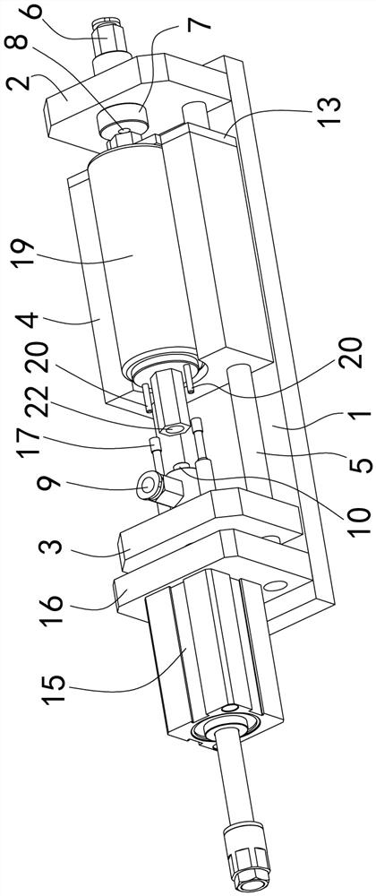
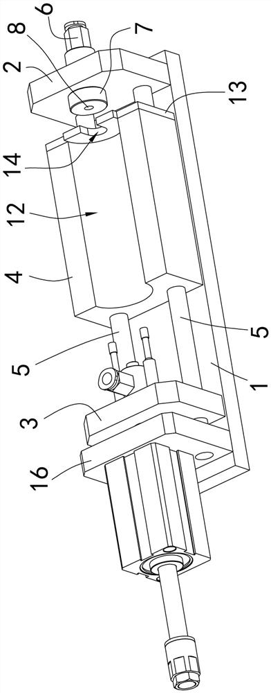
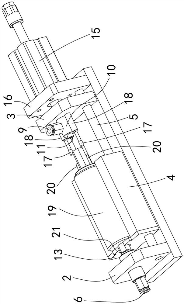
[0021] Referring to the accompanying drawings, the fuel pump degreasing tooling in the embodiment of the present embodiment includes a bracket 1, and the bracket 1 can use a bottom plate as the bracket 1, and the bracket 1 is provided with a first fixed seat 2, a first movable seat 3 and The second movable seat 4, the first movable seat 3 and the second movable seat 4 are arranged on the longitudinal track 5, so that the fi...


PUM


Abstract

A first fixed seat, a first movable seat and a second movable seat are arranged on a support, a first air connector and a first sealing block are arranged on the first fixed seat, a first longitudinal connecting hole is formed in the first sealing block, the first air connector is communicated with the first longitudinal connecting hole, and a second air connector and a second sealing block are arranged on the first movable seat. The second sealing block is provided with a second longitudinal connecting hole, and the second air connector is communicated with the second longitudinal connecting hole. The first sealing block and the second sealing block correspondingly act on an oil inlet and an oil outlet of the fuel pump respectively, when the fuel pump is clamped, a first longitudinal connecting hole in the first sealing block and a second longitudinal connecting hole in the second sealing block are connected with the oil inlet and the oil outlet of the fuel pump respectively to achieve communication, and the first sealing block and the second sealing block are connected with the oil inlet and the oil outlet of the fuel pump respectively. The second sealing block ensures connection and air tightness of the joint, the fuel pump is clamped, then ventilation is conducted for oil removal, the structural layout is reasonable, use is convenient, the fuel pump can be replaced conveniently, and oil removal and oil removal efficiency is higher.

Description

technical field [0001] The invention relates to a fuel pump degreasing tooling structure. Background technique [0002] EFI fuel pump (hereinafter referred to as fuel pump) is an important part of the fuel pump assembly. The fuel pump needs to use solvent oil (such as D60) for performance inspection and testing before leaving the factory to determine whether the fuel pump meets the specified performance requirements. Solvent oil such as D60 cannot be used in the automobile fuel system, so after the inspection is completed, the solvent oil in the fuel pump needs to be removed to avoid affecting the normal operation of the automobile fuel system and fuel pump. The solvent oil in the fuel pump can be removed by centrifugation, but its effect is poor, and there are still residues, which cannot meet the standard. Contents of the invention [0003] In view of the technical problems existing in the background technology, the technical problem solved by the present invention is t...

Claims


Application Information

Patent Timeline
Patent Type & Authority Applications(China)
IPC IPC(8): B08B5/02
CPCB08B5/02
Inventor 荣长宝张建松王晓豹
Owner WENZHOU ZOREN AUTO ELECTRIC CONTROL CO LTD
Why Eureka
Try Eureka