Forming die and forming method for blade with multi-powder structure in circumferential direction

A technology of forming molds and forming methods, which is applied in other manufacturing equipment/tools, turbines, engine components, etc., can solve the problems of inability to achieve wear resistance and impact resistance at the same time, insufficient performance of blades, and inability to achieve forming requirements, etc., to achieve Simple structure, easy operation, uniform molding effect

Pending Publication Date: 2022-05-13
SHANDONG UNIV +1
View PDF6 Cites 0 Cited by
  • Summary
  • Abstract
  • Description
  • Claims
  • Application Information

AI Technical Summary

Problems solved by technology

Generally, a device consisting of a mold body and upper and lower punches is used for powder forming, but the structure of the product formed by this device is relatively simple, and it can only be used for cutting blades with a single substrate, and cannot achieve wear resistance and impact resistance at the same time. Resulting in insufficient blade performance
Therefore, conventional molding devices and presses cannot achieve its molding requirements

Method used


Image

  • Forming die and forming method for blade with multi-powder structure in circumferential direction
  • Forming die and forming method for blade with multi-powder structure in circumferential direction
  • Forming die and forming method for blade with multi-powder structure in circumferential direction

Examples


Embodiment Construction

[0037] The present invention will be further described in detail below in conjunction with the accompanying drawings and specific embodiments.

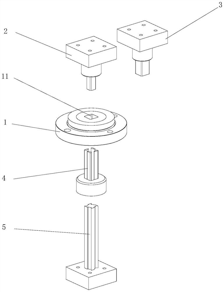
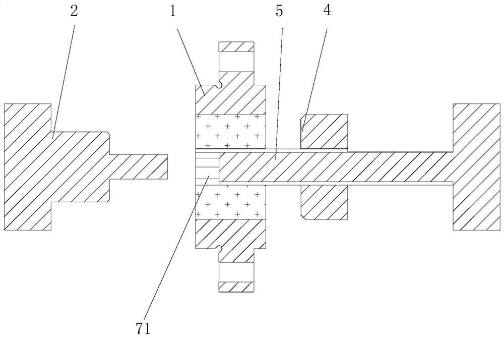
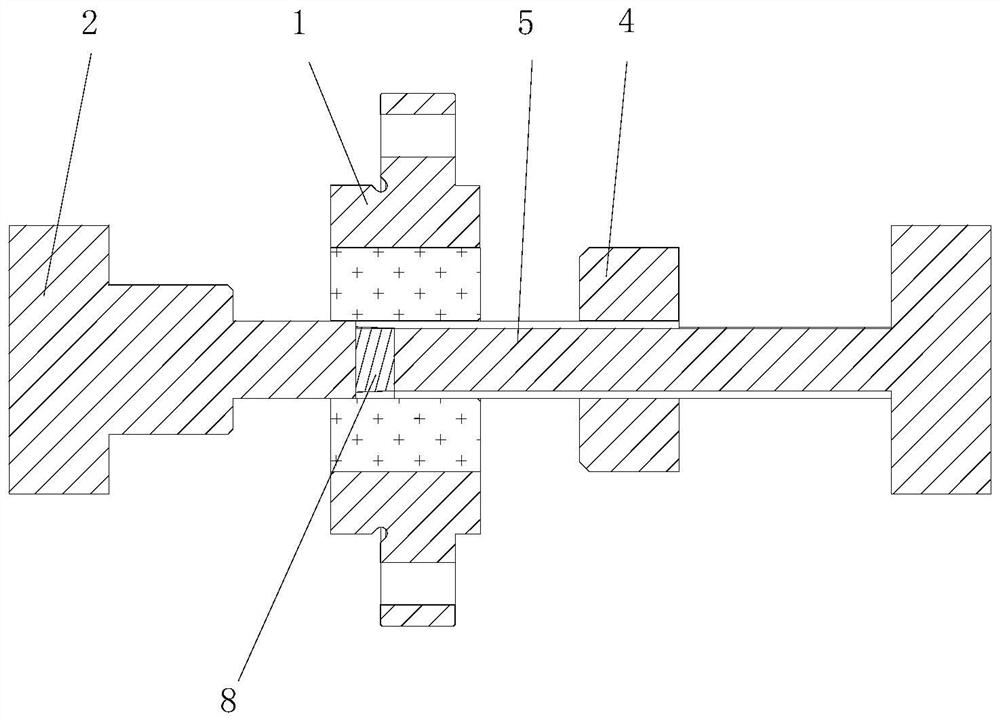
[0038] figure 1 Shown is the first embodiment of the molding die with multi-powder structure blades in the circumferential direction of the present invention, which includes a die body 1, a first upper punch 2, a second upper punch Head 3, outer lower punch 4, inner lower punch 5 and installation mold base, mold body 1 is installed on the installation mold base and can move up and down, mold body 1 is provided with a mold cavity 11, the first upper punch 2 , the second upper punch 3, the outer lower punch 4, and the inner lower punch 5 can move up and down to enter or stay away from the mold cavity 11, the first upper punch 2, the outer lower punch 4, the inner lower punch 5 and Die cavity 11 cooperates to realize the molding that circumferentially has multi-powder structure blade first circumferential matrix 61 and central matrix 63...


PUM


Abstract

The forming die comprises a die body, a first upper punch, a second upper punch, an outer lower punch, an inner lower punch and an installation die frame, the die body is installed on the installation die frame and can move up and down, a die cavity is formed in the die body, and the first upper punch, the second upper punch, the outer lower punch, the inner lower punch and the installation die frame are arranged in the die cavity. The first upper punch, the second upper punch, the outer lower punch and the inner lower punch can move up and down to enter or leave the die cavity, and the first upper punch, the outer lower punch, the inner lower punch and the die cavity are matched to achieve forming of the first circumferential base body and the center base body which are provided with the multi-powder structure blades in the circumferential direction. The second upper punch, the outer lower punch, the inner lower punch, the die cavity, the first circumferential base body and the center base body are matched to achieve forming of the second circumferential base body with the multi-powder structure blade in the circumferential direction, and the forming method comprises the steps of first-time filling, first-time pressing, first-time demolding, second-time filling, second-time pressing, second-time demolding and the like. The method has the advantages of being good in forming quality, high in applicability, convenient to operate and the like.

Description

technical field [0001] The invention mainly relates to the field of forming of metal cutting tools, in particular to a forming mold and a forming method of inserts with multi-powder structure in the circumferential direction. Background technique [0002] In powder metallurgy technology, the powder forming process is the most important process in the production of CNC blades. Generally, a device consisting of a mold body and upper and lower punches is used for powder forming, but the structure of the product formed by this device is relatively simple, and it can only be used for cutting blades with a single substrate, and cannot achieve wear resistance and impact resistance at the same time. Resulting in insufficient blade performance. Therefore conventional molding devices and presses cannot realize its molding requirements. Contents of the invention [0003] The technical problem to be solved by the present invention is to overcome the deficiencies of the prior art, to...

Claims


Application Information

Patent Timeline
Patent Type & Authority Applications(China)
IPC IPC(8): B22F3/03B22F3/00B22F5/00
CPCB22F3/03B22F3/004B22F5/00B22F2005/001B22F2003/033
Inventor 江爱胜刘战强王社权汤爱民余仁超
Owner SHANDONG UNIV
Why Eureka
Try Eureka