Assembly tool and assembly method for rudder shaft type component for ceramic-based composite aircraft

An assembly tooling and ceramic-based technology, applied in the direction of connecting components, workpiece clamping devices, manufacturing tools, etc., can solve the problem that it is difficult to meet the performance index requirements of aircraft thermal protection products, the facets of the composite skeleton and the axis of the rudder shaft are not coplanar, High precision requirements for the preparation of individual parts, etc., to achieve the effect of taking into account the realization and machinability of assembly operations, taking into account the machinability of the shaft shape, and reducing the risk of processing faults

Active Publication Date: 2022-07-26
XIAN XINGUI CERAMIC COMPOSITE MATERIAL CO LTD
View PDF6 Cites 0 Cited by
  • Summary
  • Abstract
  • Description
  • Claims
  • Application Information

AI Technical Summary

Problems solved by technology

[0006] The purpose of the present invention is to solve the cumbersome assembly process, low assembly accuracy, high requirements for the preparation accuracy of individual parts, high assembly cost and problems in the composite skeleton in the assembly method of the rudder and wing of the existing ceramic-based composite aircraft. Due to many deficiencies such as non-coplanar facets and rudder shaft axes, it is difficult to meet the technical problems of various performance index requirements of aircraft thermal protection products, and an assembly tooling and assembly method for rudder shaft components used in ceramic matrix composite aircraft is provided.

Method used


Image

  • Assembly tool and assembly method for rudder shaft type component for ceramic-based composite aircraft
  • Assembly tool and assembly method for rudder shaft type component for ceramic-based composite aircraft
  • Assembly tool and assembly method for rudder shaft type component for ceramic-based composite aircraft

Examples


Embodiment Construction

[0089] The present invention will be further described below with reference to the accompanying drawings and specific embodiments.

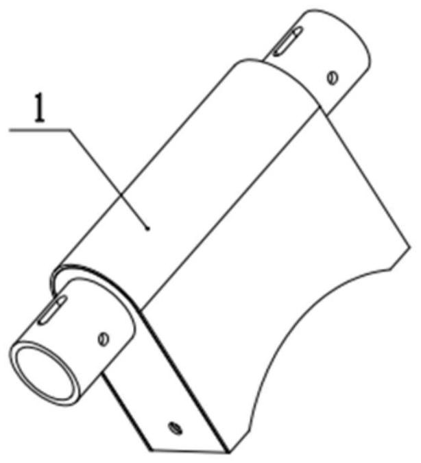
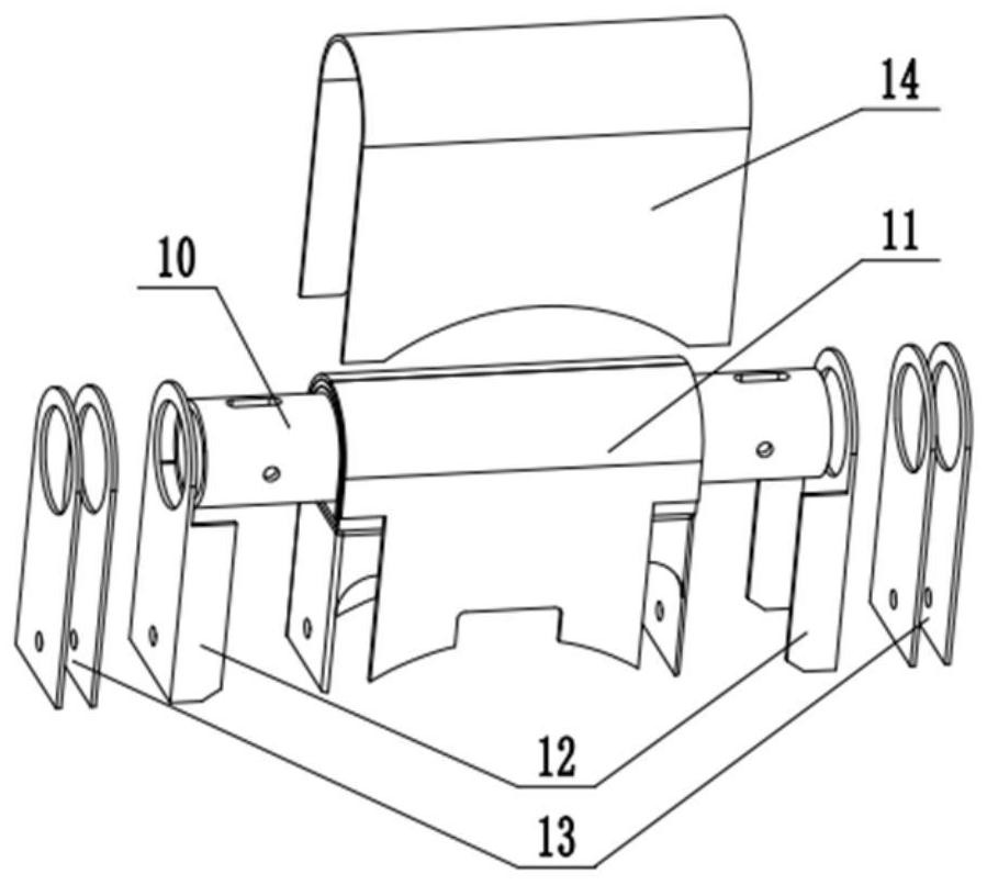
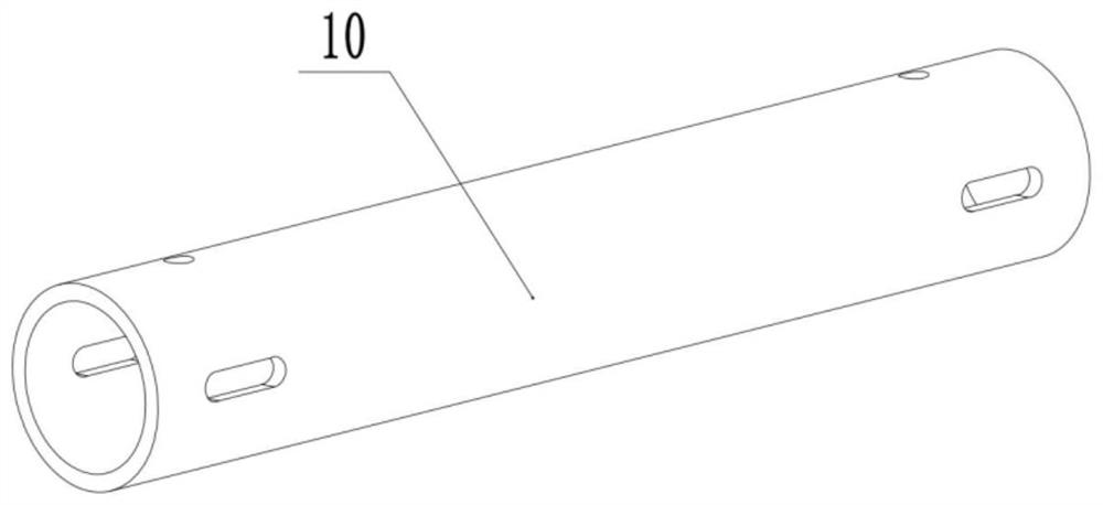
[0090] like Figure 1 to Figure 5 It is the structure of the rudder shaft member 1 to be assembled in the embodiment of the present invention. The rudder shaft member 1 is mainly composed of a rudder shaft 10 , a frame assembly 11 , a side beam assembly 12 , an ear piece assembly 13 , and a skin 14 . The side beam assembly 12 and the lug assembly 13 are respectively installed on both ends of the rudder shaft 10 . The frame assembly 11 is composed of a shaft sleeve 110, a connecting beam 111, a shaft backing plate 112, a front connecting arc plate and a rear connecting arc plate 113; the side beam assembly 12 is composed of an upper side beam 120 and a lower side beam 121; the ear piece assembly 13 is composed of Two upper ear pieces 130 and two lower ear pieces 131 are formed.

[0091] like Figure 6-Figure 17 As shown, a rudder shaft componen...


PUM


Abstract

The invention relates to a rudderpost component assembly tool, in particular to a rudderpost component assembly tool for a ceramic-based composite aircraft and an assembly method. The technical problems that an existing ceramic-based composite rudder shaft component is tedious in assembly process, poor in assembly precision and assembly quality, high in requirement for preparation of a single part and high in cost are solved. The assembly tool comprises a shaft positioning assembly and a framework assembly positioning assembly. The shaft positioning assembly comprises a bottom plate, and a V-shaped seat and a shaft pressing plate which are arranged on the bottom plate; the shaft pressing plate and the V-shaped seat are connected to form a triangular frame structure for fixing and limiting the rudder shaft; the framework assembling and positioning assembly comprises a supporting seat and a framework limiting block which are arranged on the bottom plate; a first kidney-shaped hole and a second kidney-shaped hole are formed in the supporting seat and the framework limiting block respectively, correspond to pin holes in the two sides of a connecting beam of the rudder shaft component respectively and are used for positioning the framework assembly. The invention further provides a method for assembling the rudder shaft component through the tool.

Description

technical field [0001] The invention relates to a rudder shaft component assembly tool, in particular to a rudder shaft component assembly tool and an assembly method for a ceramic-based composite aircraft, which are mainly applied to high-strength, oxidation-resistant, high-temperature-resistant composite material aircraft structure thermal protection field. Background technique [0002] Ceramic-based composite material has the advantages of metal materials, ceramic materials and carbon materials. It is a new strategic material integrating thermal structure and function. It has high temperature resistance, low density, high specific strength, high specific modulus, oxidation resistance, Ablation, insensitivity to cracks and no catastrophic damage, etc., have a wide range of applications in aviation, aerospace, satellite aerospace, nuclear energy, photovoltaics and other fields. [0003] Due to the limitation of the current composite material weaving and molding technology,...

Claims


Application Information

Patent Timeline
Patent Type & Authority Applications(China)
IPC IPC(8): B25B11/02F16B11/00
CPCB25B11/02F16B11/00Y02T50/40
Inventor 张少博马文科宋海龙康志杰何江怡姚永超都嘉鑫李仁意刘会龙赵党峰王鹏张建平付志强吴亚明
Owner XIAN XINGUI CERAMIC COMPOSITE MATERIAL CO LTD
Why Eureka
Try Eureka