Industrial automatic cutting device capable of conveniently adjusting cutting width
An industrial automation and cutting device technology, which is applied in the direction of manufacturing tools, wood processing equipment, special forming/shaping machines, etc., can solve the problems affecting the use of boards, cutting boards into different widths, etc., and achieve the effect of convenient operation
- Summary
- Abstract
- Description
- Claims
- Application Information
AI Technical Summary
Problems solved by technology
Method used
Image


Examples
Embodiment
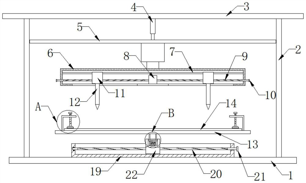
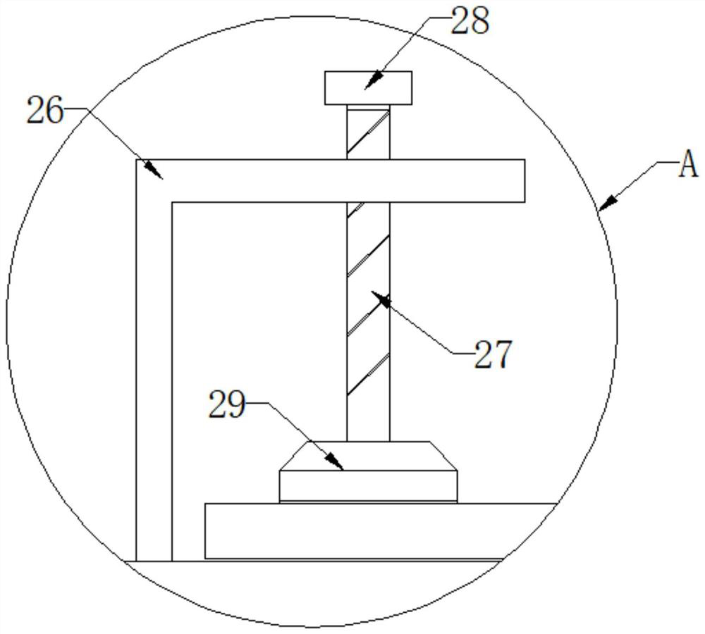
[0020] see Figure 1-4 , the present invention provides a technical solution: an industrial automatic cutting device that is convenient for adjusting the cutting width, including a bottom plate 1, two ends of the upper side wall of the bottom plate 1 are longitudinally fixed with symmetrical support plates 2, and the upper ends of the two support plates 2 The common horizontal plate 3 is fixedly arranged, the lower end of the horizontal plate 3 is longitudinally provided with a hydraulic rod 4, the upper end of the hydraulic rod 4 is fixedly connected with the lower side wall of the horizontal plate 3, and the lower end of the hydraulic rod 4 is fixedly provided with a slide plate 5, the slide plate 5 Both the left side wall and the right side wall are slidingly connected with the side walls of the two support plates 2, and the lower end of the slide plate 5 is fixedly provided with an adjustment frame 6 through a moving mechanism, and the inside of the adjustment frame 6 is ho...
PUM
 Abstract
Description
Claims
Application Information