Fan-shaped combing, flying and dyeing all-in-one machine

An all-in-one, fan-shaped technology, applied in the coating and other directions, can solve the problems of uniform stress, consuming a lot of manpower and material resources, and different sizes of round heads, so as to reduce the influence of human factors, improve quality stability, and reduce production costs. Effect

Pending Publication Date: 2022-05-13
宁波宇鸿正信智能科技有限公司
View PDF1 Cites 0 Cited by
  • Summary
  • Abstract
  • Description
  • Claims
  • Application Information

AI Technical Summary

Problems solved by technology

[0004] However, at present, it is very troublesome to fly the comb needles. The operator needs to hold the comb and put it on the fly machine to fly it. Not only the production efficiency is low, but also a lot of manpower and material resources are required. As a result, there is a problem of deviation in the size of the comb needle due to the inconsistent degree of flying hair at the tip of the comb needle, which leads to a decline in the overall quality of the comb and increases the production cost of the comb to a large extent
In addition, after the flying hair is finished, the comb needles are dyed. Since the fan-shaped comb is difficult to be uniformly stressed on the peripheral surface when dyeing the hair, it is easy to have the problem of different sizes of the round heads formed everywhere, which will affect the qualification of the comb. Rate

Method used


Image

  • Fan-shaped combing, flying and dyeing all-in-one machine
  • Fan-shaped combing, flying and dyeing all-in-one machine
  • Fan-shaped combing, flying and dyeing all-in-one machine

Examples


Embodiment Construction

[0098] The present invention will be further described in detail below with reference to the embodiments of the accompanying drawings.

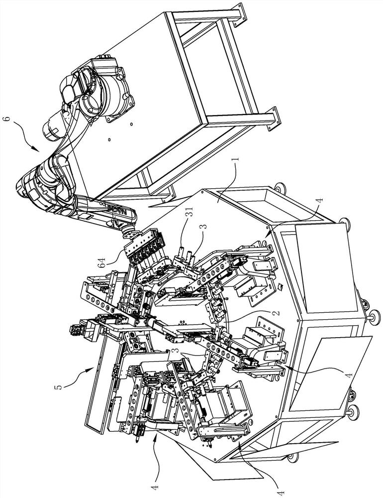
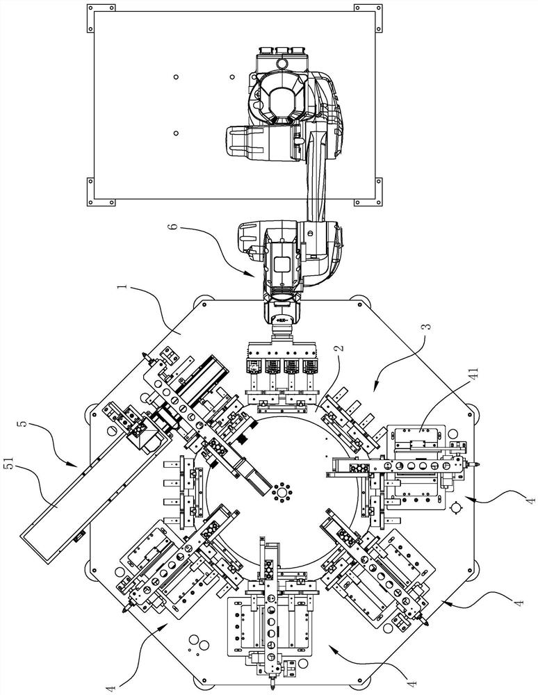
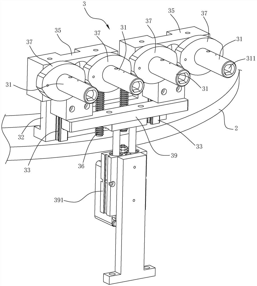
[0099] like Figures 1 to 18 As shown, the fan-shaped comb-flying-dyeing integrated machine of this embodiment includes an assembly platform 1, a turntable 2, a first driving mechanism (not shown in the figure), a positioning assembly 3, a flying hair mechanism 4, a dyeing head mechanism 5, a feeding and a lowering mechanism The feeding mechanism 6 is used to fully automatically complete the process of combing needles flying and dyeing. This embodiment can process one or more combs at the same time. In this embodiment, four combs are processed at a time. Correspondingly, the outer circumference of the turntable 2 is provided with a feeding and unloading station and four flyers from front to back according to the processing sequence. One dye head station, among which, one feeding station and one unloading station can be set for the loading an...


PUM


Abstract

The invention relates to a fan-shaped combing, flying and dyeing all-in-one machine which comprises an assembling platform, a rotating disc, a first driving mechanism, a positioning assembly, a flying mechanism, a dyeing head mechanism and a feeding and discharging mechanism. The invention provides the special automatic equipment for performing flying and head dyeing treatment on the comb needles on the fan-shaped comb, the processes of feeding, comb needle grinding and cutting, head dyeing and discharging are performed in a reciprocating manner, and structures matched with the fan-shaped structure of the comb are arranged on the positioning assembly during the comb needle grinding and cutting and head dyeing treatment, so that the comb needle grinding and cutting efficiency is improved, and the comb needle grinding and cutting efficiency is improved. The grinding and cutting amount of the card wires is always kept consistent along with the rotation of the fan-shaped structure, so that the grinding and cutting precision is effectively improved; meanwhile, the whole process does not need manual participation, so that the influence of human factors is reduced, the quality stability of combs produced in the same batch is improved, and the production cost of the combs is reduced.

Description

technical field [0001] The invention relates to the technical field of automation equipment, in particular to a fan-shaped comb-flying-dyeing integrated machine. Background technique [0002] Figure 17 , 18 A fan-shaped comb is shown, the fan-shaped comb includes a body a with a fan-shaped bottom at least and a number of comb needles b radially distributed on the fan-shaped surface a1 at the bottom of the body a, and a plurality of comb needles b are arranged in rows on the fan-shaped surface. The upper part is arranged along the length direction of the main body a, and the length of each comb needle b is slightly deviated. After the flying hair treatment, the length of the comb needle b is the same, and the lower ends of each comb needle b are arranged together on an arc-shaped surface with a larger arc than the fan-shaped surface. On d, the rear end of the main body a is provided with a handle c extending backwards. [0003] The needles of the fan-shaped comb are genera...

Claims


Application Information

Patent Timeline
Patent Type & Authority Applications(China)
IPC IPC(8): B29C41/20B29C41/34B29C69/00
CPCB29C41/20B29C41/34B29C69/001
Inventor 陈奇伟相琼颖
Owner 宁波宇鸿正信智能科技有限公司
Why Eureka
Try Eureka