Demoulding mechanism of vacuum plastic-absorbing forming mould

A technology for forming a mold and a mold release mechanism, applied in the field of mold release machines, can solve the problems affecting the overall quality of processed goods, slow internal mold forming, and reduced work efficiency, to prevent mold deformation, improve product quality, and improve mold release. the effect of efficiency

Pending Publication Date: 2022-05-13
无锡德维新精密科技有限公司
View PDF0 Cites 0 Cited by
  • Summary
  • Abstract
  • Description
  • Claims
  • Application Information

AI Technical Summary

Problems solved by technology

[0002] Blister molding can also be called vacuum forming. It is a process of processing plastics. The main principle is to heat ordinary plastics at high temperature and soften them, then use vacuum to absorb them on the surface of the mold, and then form them after cooling. It has a wide range of applications. And after molding, demoulding work is required. At present, the demoulding technology for the demoulding mechanism of the blister mold is relatively mature. However, in the existing mechanisms, the demoulding environment rarely uses a vacuum environment, and the demoulding efficiency is relatively high. Low, and the speed of internal mold forming is slow, and the quality cannot be guaranteed
[0003] Due to the existing demoulding device, the deformation of the plastic mold may be caused by improper operation during the demoulding work, which will affect the overall quality of the processed goods. Secondly, the deformation will also lead to a reduction in work efficiency, which will cause economical problems on the other hand. loss

Method used


Image

  • Demoulding mechanism of vacuum plastic-absorbing forming mould
  • Demoulding mechanism of vacuum plastic-absorbing forming mould
  • Demoulding mechanism of vacuum plastic-absorbing forming mould

Examples


Embodiment Construction

[0023] The following will clearly and completely describe the technical solutions in the embodiments of the present invention with reference to the accompanying drawings in the embodiments of the present invention. Obviously, the described embodiments are only some, not all, embodiments of the present invention. Based on the embodiments of the present invention, all other embodiments obtained by persons of ordinary skill in the art without making creative efforts belong to the protection scope of the present invention.

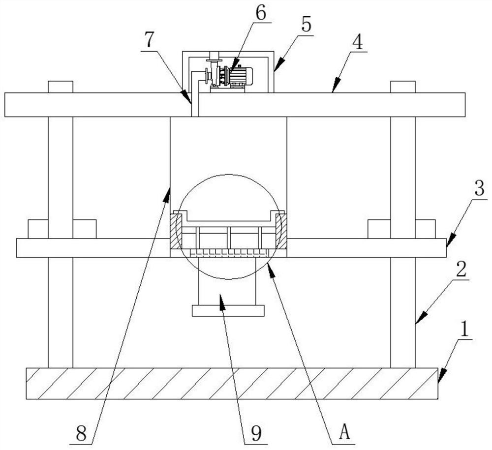
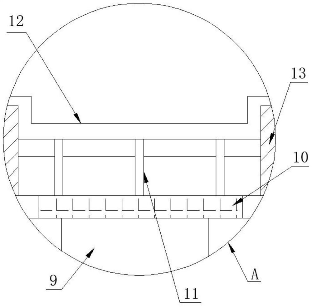
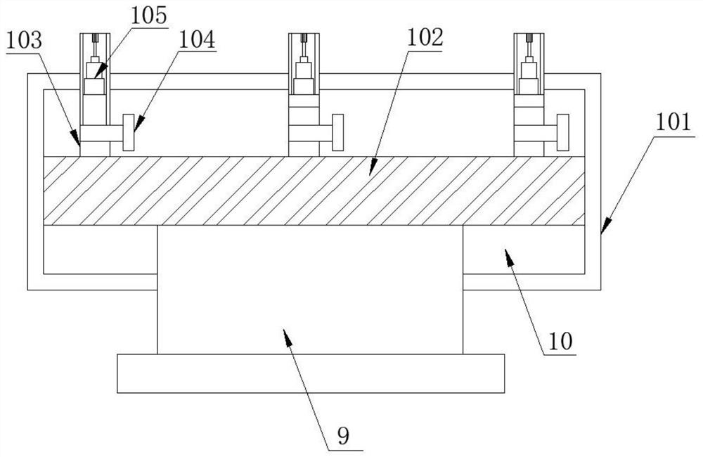
[0024] as attached figure 1 to attach Figure 5 Embodiments of the present invention provide a vacuum forming mold demoulding mechanism, including a demoulding device base 1, the left and right sides of the top of the demoulding device base 1 are fixedly connected with a stable column 2, and the middle part of the stable column 2 is fixedly connected with a working partition Layer 3, the top of the stable column 2 is fixedly welded with the working beam 4, th...


PUM


Abstract

The invention discloses a demolding mechanism for a vacuum plastic-absorbing forming mold, and particularly relates to the field of demolding machines, the demolding mechanism comprises a demolding device base, stable stand columns are fixedly connected to the left and right sides of the top of the demolding device base, a working interlayer is fixedly connected to the middle of each stable stand column, and a working cross beam is fixedly welded to the top of each stable stand column; and an air extractor is fixedly installed at the top of the working cross beam, a vacuum pump is placed in an inner cavity of the air extractor, the bottom of the vacuum pump is fixedly sleeved with an air extraction pipeline, and the bottom of the air extraction pipeline is movably sleeved with a vacuum pipe. According to the scheme, certain gas is extracted from the bottom of the demolding mechanism and injected into the vacuum pipe, deformation of a plastic mold is possibly caused by misoperation during demolding, and the overall quality of a processed commodity is affected, so that the device improves the error-tolerant rate in the demolding process by utilizing a gas injection method to prevent deformation of the mold, and the demolding efficiency is improved. The product quality is improved.

Description

technical field [0001] The invention relates to the technical field of demoulding machines, and more specifically, the invention relates to a demoulding mechanism for a vacuum suction forming mold. Background technique [0002] Blister molding can also be called vacuum forming. It is a process of processing plastics. The main principle is to heat ordinary plastics at high temperature and soften them, then use vacuum to absorb them on the surface of the mold, and then form them after cooling. It has a wide range of applications. And after molding, demoulding work is required. At present, the demoulding technology for the demoulding mechanism of the blister mold is relatively mature. However, in the existing mechanisms, the demoulding environment rarely uses a vacuum environment, and the demoulding efficiency is relatively high. Low, and the speed of internal mold forming is slow, and the quality cannot be guaranteed. [0003] Due to the existing demoulding device, the defo...

Claims


Application Information

Patent Timeline
IPC IPC(8): B29C51/44B29C51/10
CPCB29C51/44B29C51/10
Inventor 喻宗保
Owner 无锡德维新精密科技有限公司
Why Eureka
Try Eureka