
Multifunctional traction tray for road train

A road train, multi-functional technology, applied in traction connectors, vehicle parts, transportation and packaging, etc., can solve the problems of inability to meet the requirements of fast drop and hook, fast parking, short turning radius of rear trailers, inability to tow trailers, etc. The effect of avoiding trailer falling off accidents, eliminating potential transportation hazards and reducing traffic accidents

Pending Publication Date: 2022-05-13
魏连鹏
View PDF0 Cites 0 Cited by
  • Summary
  • Abstract
  • Description
  • Claims
  • Application Information

AI Technical Summary

Problems solved by technology

[0003] However, the design concept and manufacturing technology of the existing road train tractors cannot meet the basic technical requirements such as fast drop-and-hook, fast docking, and fast reorganization.
like figure 1 As shown, the radius of gyration of the existing road train is fixed, the radius of gyration of the front trailer is 3200, the radius of gyration of the tractor is 1806+1350 / 2=2481, the radius of gyration of the rear trailer is 1300, the radius of gyration of the tractor conforms to that of the front The radius of gyration of the trailer. When the tractor is dropped, it is planned to tow the rear trailer. The radius of gyration of the rear trailer is too short to be able to hook up, let alone drive.
Traditional design and manufacture lead to: fixed turning radius, unable to tow trailers with different turning radius

Method used


Image

  • Multifunctional traction tray for road train
  • Multifunctional traction tray for road train
  • Multifunctional traction tray for road train

Examples


Embodiment

[0026] The specific embodiment of the present invention is further described below in conjunction with accompanying drawing:

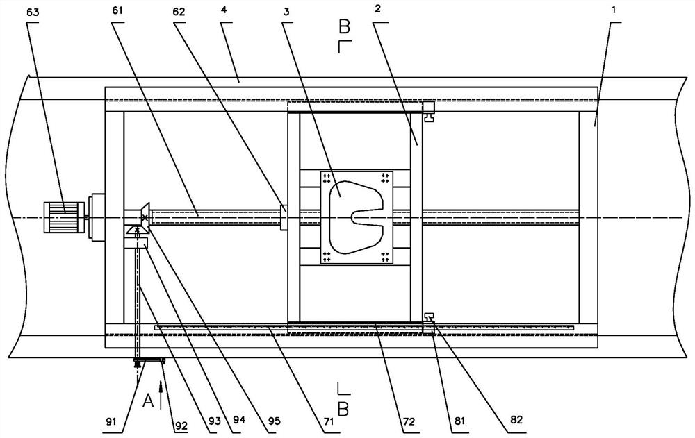
[0027] Such as Figure 2-6 As shown, a road train multifunctional traction pallet includes a main fixed bracket 1, an inner slide rail bracket 2, a traction disc 3, a slide rail assembly, a screw screw assembly, a scale assembly, a locking device and an alarm device.

[0028] The main fixing bracket 1 is a rectangular steel structure frame welded by I-beam or special-shaped I-beam. The main fixing bracket 1 is used to support the trailer load and the huge traction force of the tractor, and the steel needs to select special steel for the automobile frame.

[0029] The main fixed bracket 1 and the tractor beam 1 are bolted together, the length is about 2000mm, and the vertical load is not less than 30 tons. The main fixed bracket 1 is embedded between the two tractor beams 4, and the width is equal to the distance between the tractor beams 4.

[0030]...


PUM


Abstract

The invention relates to the technical field of road trains, in particular to a multifunctional traction tray for a road train. Comprising a main fixing support, an inner sliding rail support, a traction disc, a sliding rail combination, a spiral lead screw combination, a ruler combination and a locking device. The main fixing support is fixedly connected to a girder of a tractor, the sliding rail combination comprises a sliding rail and a sliding block, the sliding rail is fixedly connected to the main fixing support, and the sliding block is fixedly connected to the inner sliding rail support; the spiral lead screw assembly comprises a lead screw and a nut, the nut is fixedly connected to the inner sliding rail support, and the lead screw is in threaded connection with the nut. The traction disc is fixedly connected to the inner sliding rail support, the lead screw rotates to drive the inner sliding rail support and the traction disc to move along the sliding rails, the position of the traction disc is adjusted, and the traction disc is locked through the locking device after the position is determined. The turning radius can be adjusted according to needs, multiple purposes are achieved through one vehicle, throwing and hanging, stopping and recombining are fast, and the transportation efficiency is improved.

Description

technical field [0001] The invention relates to the technical field of road trains, in particular to a multifunctional traction tray for road trains. Background technique [0002] Most of the existing road train tractors are manufactured according to the traditional design concept, which can meet people’s daily use for transporting and pulling goods. The transportation activities of road train tractors are mainly reflected in transportation activities such as transportation and dumping, and generally do not separate Remove the tractor for use. In the future, with the construction of a powerful transportation country, the transportation capacity needs to be greatly improved. It is necessary to build a dense intelligent logistics industrial park to support it, so that it will be more convenient and faster to drop, reorganize, and replace drivers every 500 to 1,000 kilometers. Solve the bottleneck problems such as insufficient road transportation capacity. [0003] But, the d...

Claims


Application Information

Patent Timeline
Patent Type & Authority Applications(China)
IPC IPC(8): B60D1/14B60D1/42B60D1/28B60D1/48
CPCB60D1/14B60D1/42B60D1/28B60D1/488
Inventor 魏连鹏金珊珊张洪斌师占军侯杰
Owner 魏连鹏
Learn More