Dynamic balance automatic servo tensioner
A dynamic balance and automatic servo technology, which is applied in the field of servo tensioner and dynamic balance automatic servo tensioner, can solve the problems of affecting normal work, not having internal servo device for dust-free heat dissipation, affecting the safety of internal components, etc., to improve safety Effect
- Summary
- Abstract
- Description
- Claims
- Application Information
AI Technical Summary
Problems solved by technology
Method used
Image
Examples
Embodiment 1
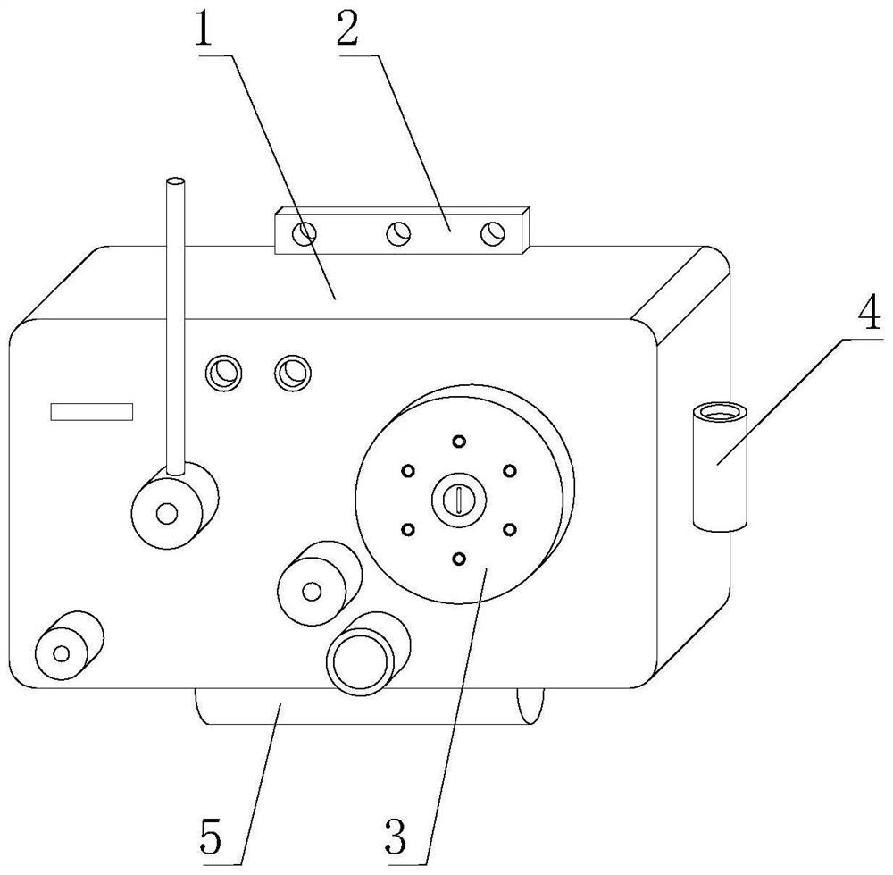
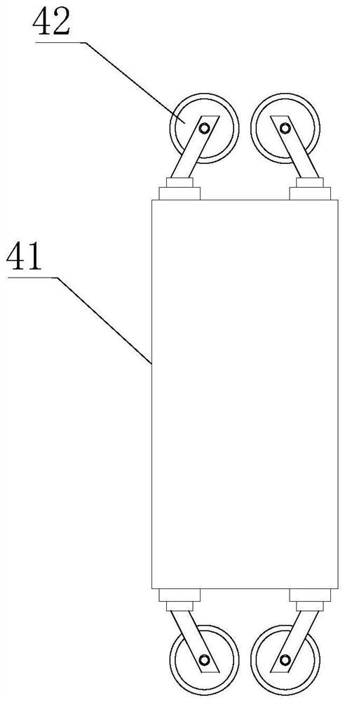
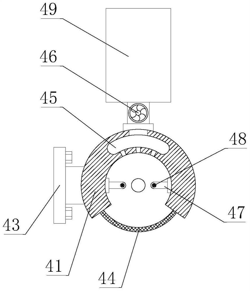
[0035] Such as Figure 1-9As shown, the present invention provides a dynamic balance automatic servo tensioner, comprising a dynamic balance tensioner body 1, the front of the dynamic balance tensioner body 1 is provided with a driving wheel 3, and the top of the dynamic balance tensioner body 1 is fixedly welded with an installation Plate 2, the right side of the dynamic balance tensioner body 1 is provided with a silk thread removal mechanism 4, the bottom of the dynamic balance tensioner body 1 is provided with a gas circulation heat dissipation mechanism 5, the silk thread removal mechanism 4 includes a vertical cylinder 41, the vertical cylinder The top and the bottom of 41 are fixedly equipped with guide wheels 42, the left side of the vertical tube 41 is fixedly welded on the connecting seat 43, and the connecting seat 43 is detachably connected to the right side of the dynamic balance tensioner body 1, and the front side of the vertical tube 41 A screen plate 44 is fix...
Embodiment 2
[0037] Such as Figure 1-9 As shown, on the basis of Embodiment 1, the present invention provides a technical solution: preferably, an elastic member 481 is fixedly installed on the outer wall of the rotating rod 48, and the end of the elastic member 481 away from the rotating rod 48 is fixedly connected with a rubber swing bar 482, the outer wall of the rotating rod 48 is fixedly equipped with a wind capture cover 483, the back side of the suction fan 46 is fixedly connected with a water bath box 49, and the front of the water bath box 49 inner cavity is fixedly installed with a splitter wind plate 491, and the inside of the splitter wind plate 491 is opened. There is a shunt groove 492, the design of the guide wheel 42 can make the silk thread pass through the inner cavity of the vertical cylinder 41 in advance, control the work of the suction fan 46, and absorb air from the inner cavity of the vertical cylinder 41, and the air can be captured by the wind force capture cover ...
Embodiment 3
[0039] Such as Figure 1-9 Shown, on the basis of embodiment 1, the present invention provides a kind of technical scheme: preferably, the top of water bath box 49 is fixedly installed with miniature circulation pump 493, and the outlet pipe of miniature circulation pump 493 is fixedly connected with the top of water bath box 49 , the top of the water bath box 49 inner cavity is fixedly connected with a shower nozzle 494, the back side of the water bath box 49 is fixedly connected with an inclined exhaust pipe, the bottom of the water bath box 49 is fixedly connected with a water storage cylinder 495, the water inlet pipe of the micro circulation pump 493 and the water storage cylinder The bottom of 495 is fixedly connected, and an inclined plate 4951 is fixedly welded in the inner cavity of the water storage cylinder 495. The top of the inclined plate 4951 is fixedly equipped with a filter cover 4952. The front of the water storage cylinder 495 is detachably connected with a c...
PUM
 Abstract
Description
Claims
Application Information
 - R&D
- Intellectual Property
- Life Sciences
- Materials
- Tech Scout
- Unparalleled Data Quality
- Higher Quality Content
- 60% Fewer Hallucinations
Browse by: Latest US Patents, China's latest patents, Technical Efficacy Thesaurus, Application Domain, Technology Topic, Popular Technical Reports.
© 2025 PatSnap. All rights reserved.Legal|Privacy policy|Modern Slavery Act Transparency Statement|Sitemap|About US| Contact US: help@patsnap.com


