An anti-cavitation regulating valve with balanced pressure function

A pressure-balancing and regulating valve technology, applied in the field of regulating valves, can solve problems such as the reduction of the flow area, the influence of the basic regulating function of the valve, and the degree of harm, so as to achieve the effect of maintaining the pressure balance and stability

Active Publication Date: 2022-06-21
艾肯(江苏)工业技术有限公司
View PDF6 Cites 0 Cited by
  • Summary
  • Abstract
  • Description
  • Claims
  • Application Information

AI Technical Summary

Problems solved by technology

[0004] At the over-current position in the regulating valve, the over-current pressure drop is often adjusted through the annular throttling gap formed by the valve core and the valve body, and the outlet pressure is adjusted to be stable. The opening and the over-flow gap are small. Although the flow rate is reduced due to throttling, the over-flow area is reduced more. The flow rate is relatively high. As the opening is further reduced, the flow rate decreases faster, and the flow rate decreases accordingly. But at this time, it has reached the micro flow condition (the valve diameter corresponds to the first 0.5% of the flow range), even if Cavitation occurs, the number of bubbles is small, and the degree of harm is not great. The cavitation that occurs at low flow rate is the stage that most needs to prevent cavitation. In this stage, the number of bubbles is enough to cause a large degree of damage to the metal wall surface. Moreover, The regulating valves in the prior art generally have only one flow channel with an annular gap, and the annular gap is also the sealing surface when the valve is fully closed. If cavitation occurs at low flow rate and the sealing surface is damaged, the basic regulation of the valve function will be affected

Method used


Image

  • An anti-cavitation regulating valve with balanced pressure function
  • An anti-cavitation regulating valve with balanced pressure function
  • An anti-cavitation regulating valve with balanced pressure function

Examples


Embodiment Construction

[0039] The technical solutions in the embodiments of the present invention will be clearly and completely described below with reference to the accompanying drawings in the embodiments of the present invention. Obviously, the described embodiments are only a part of the embodiments of the present invention, but not all of the embodiments. Based on the embodiments of the present invention, all other embodiments obtained by those of ordinary skill in the art without creative efforts shall fall within the protection scope of the present invention.

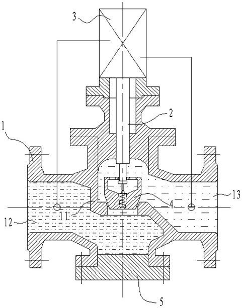
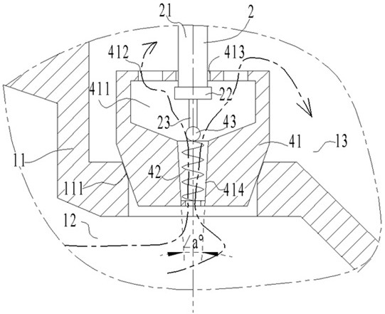
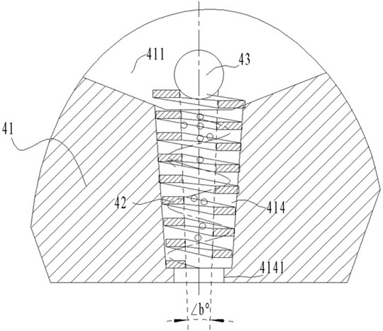
[0040] see Figure 1-Figure 4 , the present invention provides technical scheme:

[0041] An anti-cavitation regulating valve with balanced pressure function, comprising a valve body 1, a valve stem 2, a regulator 3, and a valve core 4, the valve body 1 includes a casing and a bent partition 11 arranged in the casing. The layer 11 divides the housing into the inlet channel 12 and the outlet channel 13, the main flow hole 111 in the v...


PUM


Abstract

The invention discloses the field of regulating valves, in particular to an anti-cavitation regulating valve with the function of balancing pressure, which includes a valve body, a valve stem, a regulator, and a valve core. The interlayer separates the shell into the inlet and outlet flow channels. The main flow hole in the vertical direction is set in the middle of the interlayer. The valve stem is installed vertically on the upper part of the valve body. The main flow hole, the regulator is set on the upper end of the valve body and connected to the upper end of the valve stem; the center of the valve core is equipped with a cylindrical auxiliary flow channel, the auxiliary flow channel in the spool has a spiral flow structure, and the auxiliary flow channel in the spool The flow channel is closed later than the main flow hole, and the auxiliary flow channel in the valve core is opened earlier than the main flow hole. By setting an additional spiral auxiliary passage in the spool as a passage for the small flow of the regulating valve, the liquid only flows in the spool within the flow range where cavitation occurs, and the air bubbles generated by cavitation are expelled to the spring hole Central open position to prevent cavitation damage.

Description

technical field [0001] The invention relates to the technical field of regulating valves, in particular to an anti-cavitation regulating valve with a function of balancing pressure. Background technique [0002] A large number of valves need to be used in industrial pipelines. For the liquid conveying process section, cavitation and water hammer are two situations that need to be prevented. Among them, cavitation mostly occurs at the impeller of the liquid booster pump, and water hammer generally occurs. Before the on-off valve of the main line. In the prior art, there are relatively mature structural designs for the anti-cavitation at the pump position and the waterproof hammer at the valve position to prevent damage. [0003] However, the position of the regulating valve on the steam condensate pipeline is also a position where cavitation may occur. Cavitation is mainly due to the cavitation of liquid under certain conditions to form clusters of bubbles, and the pressure ...

Claims


Application Information

Patent Timeline
Patent Type & Authority Patents(China)
IPC IPC(8): F16K47/02F16K39/02F16K17/06F16K17/168
CPCF16K47/023F16K39/024F16K17/06F16K17/0406F16K17/168
Inventor 黄益华张祺午葛剑郝刚
Owner 艾肯(江苏)工业技术有限公司
Why Eureka
Try Eureka