Clean environment system and method

An environmental system, clean technology, applied in the field of clean environment system, can solve problems such as air pollutants, inability to meet epidemic control, hidden dangers, etc.

Pending Publication Date: 2022-05-13
SHANGHAI BIXIUFU ENTERPRISE MANAGEMENT CO LTD
View PDF0 Cites 0 Cited by
  • Summary
  • Abstract
  • Description
  • Claims
  • Application Information

AI Technical Summary

Problems solved by technology

Due to house design, indoor use of air, etc., the room is generally in a negative pressure state. When doors and windows are opened or people enter, a large amount of untreated outdoor air will flow into the room, bringing air pollutants and causing indoor air pollution. Pollution
Even if it is not in smoggy weather, there are various viruses in the air. If the inflowing airflow is not intervened, a large amount of air pollutants will be brought into the room when the user enters and exits the house, polluting the indoor air, not only failing to meet the requirements of epidemic control , and there is a hidden danger of infectious bacteria
[0004] On the other hand, the current air purification system has a complex structure and single function, and the effect of dust removal, virus and bacteria removal, or negative oxygen ion generation is not satisfactory, and it cannot meet the air quality improvement of the entire indoor environment space.

Method used


Image

  • Clean environment system and method
  • Clean environment system and method
  • Clean environment system and method

Examples


Embodiment 1

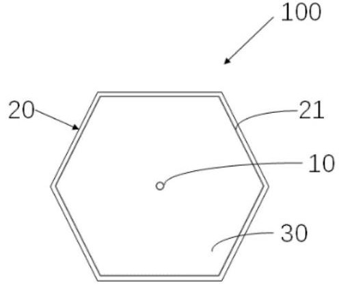
[0214] figure 1 It is a schematic cross-sectional view of an electric field unit according to an embodiment of the present invention. The electric field unit 100 is used to perform electric field treatment on gas to perform decontamination treatment on gas, including a first pole 10 and a second pole 20 for forming an electric field, wherein , a gas channel 30 is formed between the first pole 10 and the second pole 20 to allow gas to pass through and perform electric field treatment, and the electric field unit 100 satisfies one or more of the following three conditions, and / or satisfies the following three features One or more of:

[0215] First condition: refer to figure 1 , the second pole 20 is a hollow tube, and the diameter of the inscribed circle of the hollow tube is less than or equal to 30 mm. When the diameter of the inscribed circle is less than or equal to 30 mm, the decontamination efficiency is good (no germs are detected), and the negative oxygen ions are incr...

Embodiment 2

[0246] In one embodiment of the present invention, an electric field treatment device is provided, including at least one electric field unit.

[0247] It should be emphasized that the electric field unit of the electric field processing device is the same as the electric field unit of the foregoing embodiment 1 and will not be described in detail, and only the arrangement of the electric field unit in the electric field processing device will be described below.

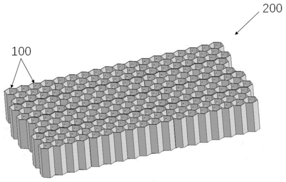
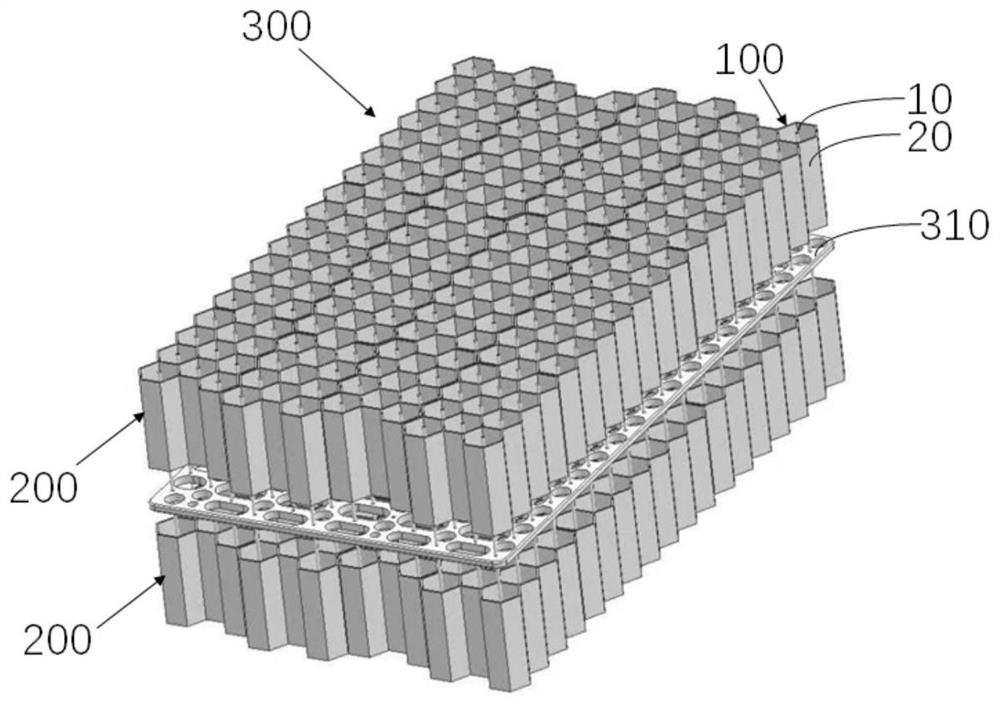
[0248] figure 2 is a schematic diagram of an electric field module according to an embodiment of the present invention, refer to figure 1 and figure 2 , the second pole 20 is a hollow tube, and the number of electric field units 100 is n in total, and each m electric field units 100 form at least one electric field module 200 arranged in sequence along the airflow direction, wherein n is greater than or equal to m, and m is greater than 1. In this embodiment, the electric field processing device includes one ele...

Embodiment 3

[0267] like Figure 4 and Figure 5 As shown, the building includes a room 3, and this embodiment provides an indoor fresh air system, including an indoor air intake device 2, and the indoor air intake device 2 performs a first decontamination treatment on the air entering the room 3 from the outside before entering the room 3.

[0268] The above-mentioned exterior is not limited to outdoors.

[0269] In one embodiment, the indoor air inlet device 2 is respectively connected with the outdoor 4 and the indoor 3, and is used to allow the air in the outdoor 4 to enter the indoor after the first decontamination treatment. 3.

[0270] In one embodiment, the indoor air intake device 2 has at least one air inlet (not shown in the figure) communicating with the indoor 3, and the air in the indoor 3 can enter the indoor through the air inlet. The air inlet device 2 enters the chamber 3 after performing the first decontamination treatment.

[0271] In one embodiment, the indoor air ...


PUM


Abstract

According to the environment cleaning system and method, the environment cleaning system comprises a room with clean air, and the clean air is obtained by conducting electric field treatment on air entering the room and/or indoor air through an electric field treatment part; the buffer space is arranged between the indoor space and the outdoor space; wherein the buffer space is used as a transition from the outdoor space to the indoor space, and clean air in the indoor space is input into the buffer space through positive pressure so as to prevent the outdoor air from entering the buffer space.

Description

technical field [0001] The invention relates to a clean environment system and method. Background technique [0002] In recent years, with the improvement of living standards and changes in lifestyles, people spend more and more time indoors, and the quality of indoor air directly affects people's work and life. [0003] In winter or in weather such as smog, the outdoor air contains a large amount of air pollutants. When the door or window of the house is opened, the poor outdoor air will enter the room. Due to house design, indoor use of air, etc., the room is generally in a negative pressure state. When doors and windows are opened or people enter, a large amount of untreated outdoor air will flow into the room, bringing air pollutants and causing indoor air pollution. Pollution. Even if it is not in smoggy weather, there are various viruses in the air. If the inflowing airflow is not intervened, a large amount of air pollutants will be brought into the room when the use...

Claims


Application Information

Patent Timeline
Patent Type & Authority Applications(China)
IPC IPC(8): F24F8/192F24F7/003F24F7/08
CPCF24F7/08
Inventor 奚勇
Owner SHANGHAI BIXIUFU ENTERPRISE MANAGEMENT CO LTD
Why Eureka
Try Eureka