Method for manufacturing multi-angle V-shaped or U-shaped crack of tensile soil sample

A production method and multi-angle technology, which are applied in the preparation, sampling, and instrumentation of test samples, can solve the problems of low tensile strength, inconvenience, and difficulty in prefabrication, avoid processing and trimming, and achieve simple and convenient operation. Create quick effects

Pending Publication Date: 2022-05-13
NANJING INST OF TECH
View PDF0 Cites 0 Cited by
  • Summary
  • Abstract
  • Description
  • Claims
  • Application Information

AI Technical Summary

Problems solved by technology

[0005] These methods are mainly designed for the soil sample of the compressive test of the soil, and not specifically for the tensile soil sample. After all, the tensile strength of the soil is lower than the compressive strength, and it is more easily disturbed by external forces. If you still use a blade or Hacksaw prefabricated the cracks in the middle of the stretched soil samples, not only it is difficult to accurately make cracks that meet the test requirements, but also it is very inconvenient to operate and easily interferes with the original state of the soil samples, affecting the test results. The shape and sample preparation method of the pressed soil sample are also different. The above method is difficult to realize the prefabrication of cracks at different positions and angles in the tensile soil sample, and the development of cracks with different positions, different inclination angles and different crack tip forms in the soil The law of influence is the primary prerequisite for comprehensively studying the tensioning problem of soil with cracks, so the present invention aims at the deficiencies of the above prefabrication methods, and proposes a multi-crack prefabrication method for tensile soil samples. It not only avoids the influence of layer-by-layer compaction, but also is easy to operate and can meet the prefabrication of cracks at different angles, different crack tip forms, and different positions.

Method used


Image

  • Method for manufacturing multi-angle V-shaped or U-shaped crack of tensile soil sample
  • Method for manufacturing multi-angle V-shaped or U-shaped crack of tensile soil sample
  • Method for manufacturing multi-angle V-shaped or U-shaped crack of tensile soil sample

Examples


Embodiment Construction

[0034] In order to make the technical means, creative features, goals and effects achieved by the present invention easy to understand, the present invention will be further described below in conjunction with specific embodiments.

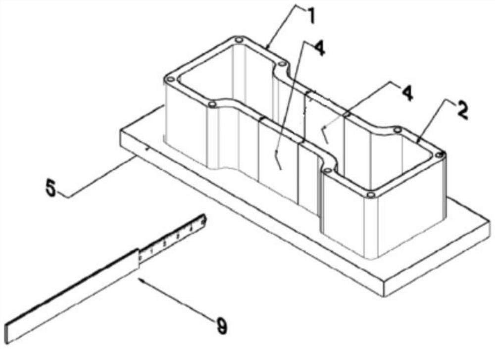
[0035] Such as Figure 1-11 As shown, a method for making multi-angle V or U-shaped cracks in tensile soil samples comprises the following steps:

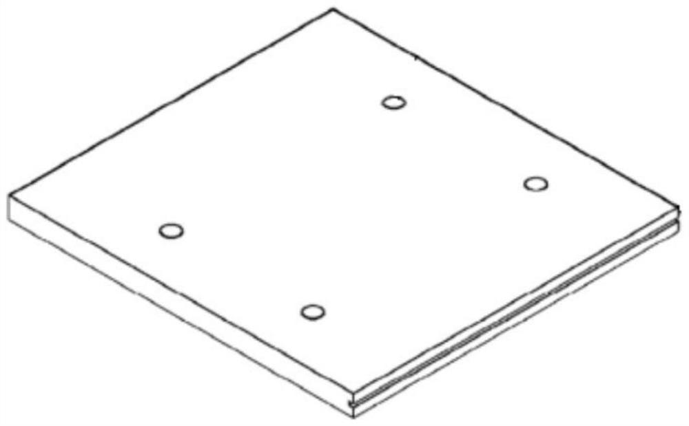
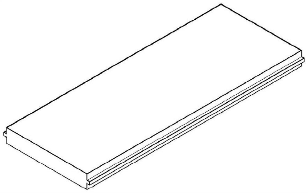
[0036] A01: First assemble the tensile soil sample mold, assemble the left bottom plate, the middle bottom plate, and the right end bottom plate together through the card slots, and use bolts to fix the left end clamping mold 1 and the right end clamping mold 2 respectively on the left end bottom plate and the right end bottom plate , and then insert two baffle plates 4 without cracks into the mold through the slot, place soil samples in the mold, the width and length of the two cracks can be designed and manufactured according to the test requirements, and the width of the cracks here is 0.5mm. The l...


PUM

PropertyMeasurementUnit
widthaaaaaaaaaa
lengthaaaaaaaaaa

Abstract

The invention discloses a method for manufacturing a multi-angle V-shaped or U-shaped crack of a tensile soil sample, and belongs to the technical field of geotechnical tests of geotechnical engineering, and the method comprises the following steps: A01, firstly, assembling a tensile soil sample mold, assembling a left end bottom plate, a middle bottom plate and a right end bottom plate together through clamping grooves, then inserting two baffle plates without crack gaps into the mold through the clamping grooves, and forming a tensile soil sample mold; placing a soil sample in the mold; a02, after the soil sample is compacted layer by layer through a compaction rod, the two baffles without crack notches are taken down, and the two baffles with crack notches are inserted again; a03, inserting the soil sample through the crack gap by using a cutter; a04, the baffle and the bottom plate are taken down, the clamping section mold is reserved, pulling force is applied to the two ends of the clamping section mold, and the exposed stretching section soil sample containing the prefabricated crack is the final soil sample needed by the test. Crack notches are prefabricated in the front baffle and the rear baffle, the accuracy of crack positions, inclination angles, sizes and crack tip shapes in soil samples is guaranteed, and repeated machining and finishing are avoided.

Description

technical field [0001] The invention relates to the technical field of geotechnical engineering geotechnical tests, in particular to a method for making multi-angle V or U-shaped cracks in tensile soil samples. Background technique [0002] Because the low tensile strength of the soil is not used as the design basis, the impact on safety and stability in actual engineering is easily ignored, resulting in the influence of soil, especially cohesive soil, due to drying shrinkage, lateral stress reduction or differential settlement. The tensile stress in the soil exceeds the tensile strength and local tension cracks appear, which in turn causes a large number of geotechnical and geological engineering problems. For example, the drying shrinkage of the soil and tension cracks will cause the bearing capacity of the foundation soil to decline, affecting the superstructure For the safety of the structure, the tension cracks in the clay core wall of the embankment will lead to leakag...

Claims


Application Information

Patent Timeline
Patent Type & Authority Applications(China)
IPC IPC(8): G01N1/28G01N1/36
CPCG01N1/28G01N1/286G01N1/36
Inventor 王伟
Owner NANJING INST OF TECH
Why Eureka
Try Eureka