
Visual inspection system of TFT display screen

A visual inspection and display technology, applied in the manufacturing of electrical components, circuits, semiconductor/solid-state devices, etc., can solve the problem that affects the accuracy of TFT display inspection results, the detection light cannot meet the optimal detection requirements, and affects the detection efficiency of the detection system. and other problems to achieve the effect of increasing convenience, improving accuracy, and simple and convenient operation.

Pending Publication Date: 2022-05-13
邱翠虹
View PDF0 Cites 0 Cited by
  • Summary
  • Abstract
  • Description
  • Claims
  • Application Information

AI Technical Summary

Problems solved by technology

[0003] In the production process of TFT display screens, it is necessary to perform a visual test on the display screen to detect whether there are defects in each pixel of the display screen, and to observe and judge whether the display screen can display images normally. The detection process needs to be carried out in a dark environment. The existing detection device Most of the display screens are put into the detection chamber for detection, but most of the existing detection chambers are not sealed, so that the detection light cannot meet the best detection requirements, which affects the accuracy of the test results of the TFT display screen; in addition, the existing detection chamber Most of them cannot automatically adjust the position of the TFT display screen. In order to ensure the detection effect of the detection system, the staff needs to adjust the position of the TFT display screen placed in the detection chamber to ensure that the TFT display screen is located in the middle of the detection chamber. Not only the operation It is cumbersome and affects the detection efficiency of the detection system

Method used


Image

  • Visual inspection system of TFT display screen
  • Visual inspection system of TFT display screen
  • Visual inspection system of TFT display screen

Examples


Embodiment Construction

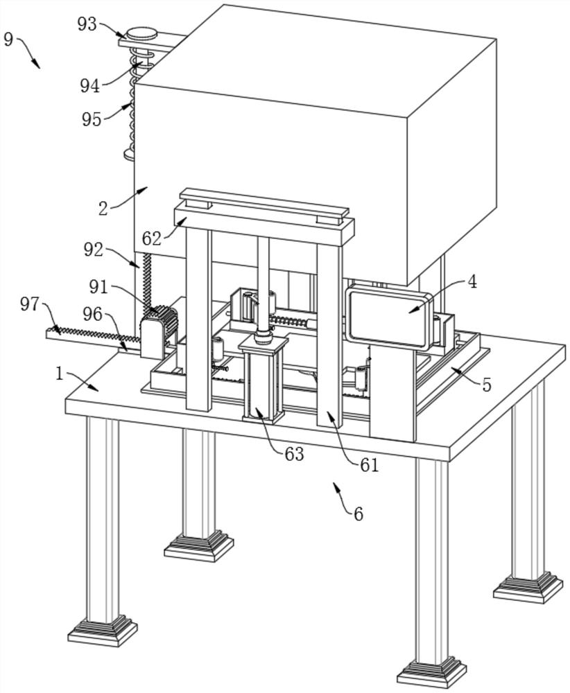
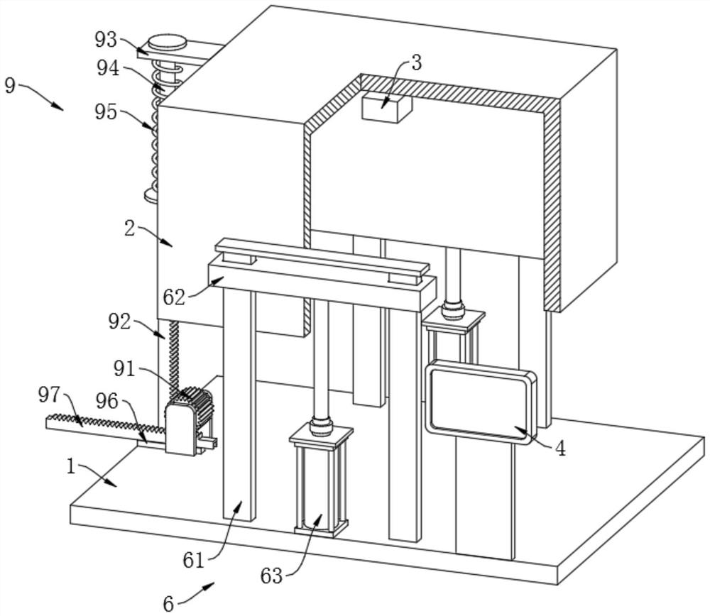
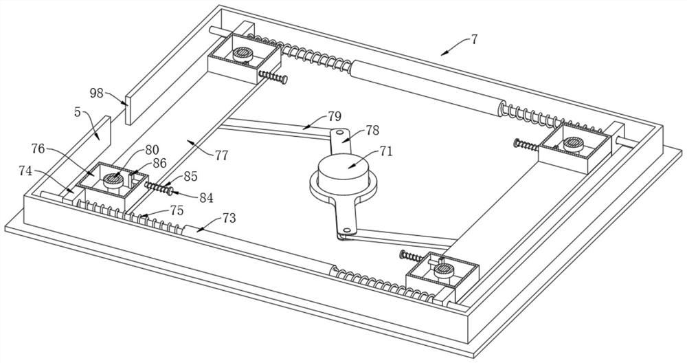
[0026] In order to make the purpose, technical solutions and advantages of the embodiments of the present invention more clear, the technical solutions in the embodiments of the present invention will be clearly and completely described below in conjunction with the accompanying drawings in the embodiments of the present invention. Obviously, the described embodiments It is a part of embodiments of the present invention, but not all embodiments. Based on the embodiments of the present invention, all other embodiments obtained by persons of ordinary skill in the art without making creative efforts belong to the protection scope of the present invention.

[0027] The invention provides a visual detection system of a TFT display screen, such as Figure 1-Figure 5 As shown, the detection platform 1 is provided with a detection chamber 2 above the detection platform 1, and a light intensity sensor 3 is provided at the top end of the inner wall of the detection chamber 2. One side o...


PUM


Abstract

The invention discloses a visual detection system of a TFT display screen, and relates to the technical field of visual detection of TFT display screens. The system comprises a detection table, a detection bin is arranged above the detection table, a light intensity sensor is arranged at one end of the top of the inner wall of the detection bin, a detection data display screen used in cooperation with the detection bin is arranged on one side of the detection table, and a shading frame used in cooperation with the detection bin is fixedly connected to one end of the top of the detection table; the detection bin and the detection table are connected through a lifting device, and a self-centering device used in cooperation with the detection bin is arranged at one end of the top of the detection table. By arranging the lifting device, the detection bin can be lifted and moved, the detection environment is in a dark sealed state, the standard environment during TFT display screen detection is guaranteed, the accuracy of the detection result of the visual detection system can be effectively improved, the operation is simple and convenient, and the use convenience of the visual detection system is improved.

Description

technical field [0001] The invention belongs to the technical field of visual detection of TFT display screens, in particular to a visual detection system of TFT display screens. Background technique [0002] TFT is thin film field effect transistor. The so-called thin film transistor means that each liquid crystal pixel on the liquid crystal display is driven by a thin film transistor integrated behind it. In this way, high-speed, high-brightness, and high-contrast display screen information can be achieved. TFT is an active matrix liquid crystal display. [0003] In the production process of TFT display screens, it is necessary to perform a visual test on the display screen to detect whether there are defects in each pixel of the display screen, and to observe and judge whether the display screen can display images normally. The detection process needs to be carried out in a dark environment. The existing detection device Most of the display screens are put into the det...

Claims


Application Information

Patent Timeline
Patent Type & Authority Applications(China)
IPC IPC(8): H01L21/67H01L21/687
CPCH01L21/68721H01L21/67242
Inventor 邱翠虹
Owner 邱翠虹
Learn More