

Ultra-narrow-band electromagnetic wave asymmetric transmission super-structure device
An asymmetric and electromagnetic wave technology, which is applied in the field of artificial electromagnetic materials and terahertz science, can solve problems such as the inability to realize asymmetric transmission of electromagnetic waves with a single frequency, and achieve the effect of asymmetric transmission and high circular dichroism
- Summary
- Abstract
- Description
- Claims
- Application Information
AI Technical Summary
Problems solved by technology
Method used
Image

Examples
Embodiment 1
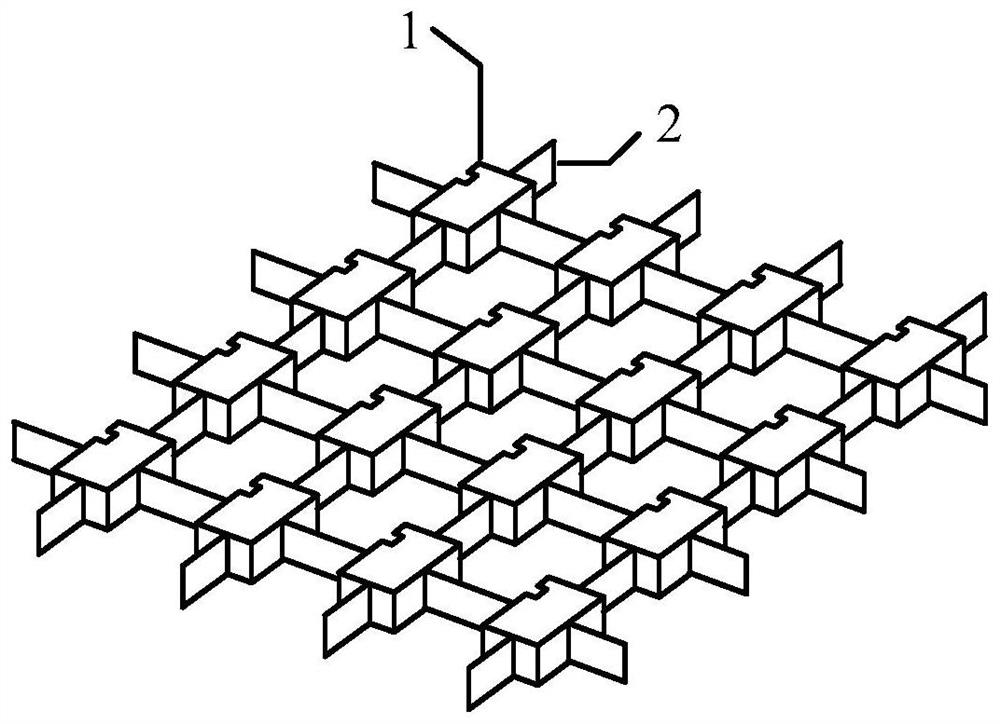
[0024] An ultra-narrow-band electromagnetic wave asymmetric transmission meta-device, such as figure 1 As shown, rectangular asymmetric opening blocks 1 arranged periodically in N rows and M columns are connected by connectors 2; both N and M are positive integers.
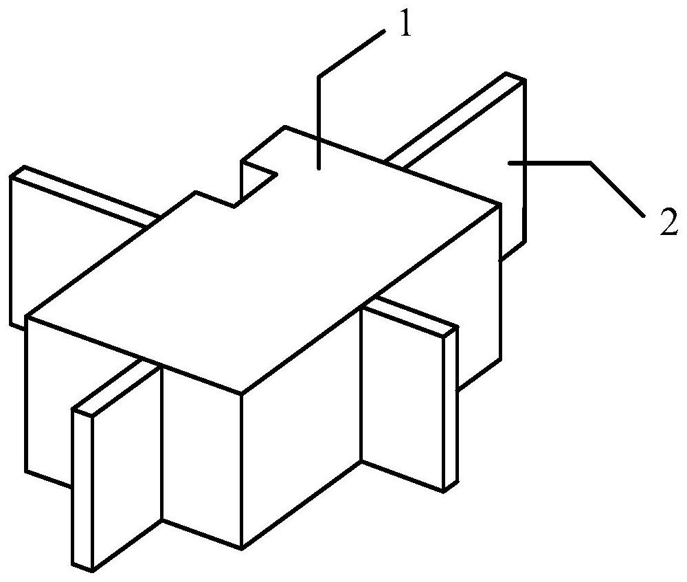
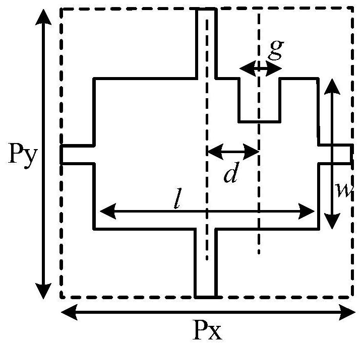
[0025] Such as figure 2 and image 3 As shown, the length l of the rectangular asymmetric opening block 1 is 90 μm, the width w is 60 μm, and its long side has a square opening, the size g of the square opening is 8 μm, the distance between the center of the square opening and the geometric center of the rectangular asymmetric opening block 1 d is 18 μm.
[0026] The rectangular asymmetrical opening block 1 and the connecting piece 2 are made of high-resistance silicon with a thickness of 50 μm.
[0027] The row period constant Px and the column period constant Py of each rectangular asymmetric opening block 1 are both 160 μm.
[0028] The rectangular asymmetric opening block provided by this embodiment belon...
Embodiment 2
[0031] On the basis of the above-mentioned embodiment 1, the rectangular asymmetric opening block 1 and the connecting piece 2 are made of high-resistance silicon material with a dielectric constant of 11.9, so that the operating frequency of the device is 1.47187 THz, and the diffraction-limited frequency is 1.87 THz.
[0032] In this field, the absolute value of circular dichroism (CD), which describes the asymmetric transport properties of metasurfaces, is a function related to the bound state frequency ω 0 and radiation rate γ 0 The related functions are expressed as:
[0033]
[0034] where m 1 ,m 2 ,n 1 ,n 2 Determined by the structural parameters and not equal to each other, it represents the coupling coefficient between the circularly polarized eigenmode of the device and the external circularly polarized excitation wave. The device design of this embodiment aims to make the absolute value of CD peak at the operating frequency of 1.47187 THz, and the peak width...
PUM
| Property | Measurement | Unit |
|---|---|---|
| Thickness | aaaaa | aaaaa |
Abstract
Description
Claims
Application Information