
Microstrip patch antenna

A technology of microstrip patch antenna and radiation patch, which is applied in the direction of antenna, antenna grounding device, antenna grounding switch structure connection, etc., can solve the problems of little effect, meet the requirements of low profile and omnidirectionality, and broaden the impedance The effect of wide bandwidth and good omnidirectional radiation

Pending Publication Date: 2022-05-13
FAW VOLKSWAGEN AUTOMOTIVE CO LTD
View PDF0 Cites 0 Cited by
  • Summary
  • Abstract
  • Description
  • Claims
  • Application Information

AI Technical Summary

Problems solved by technology

[0002] With the widespread popularization of family cars, the number of vehicles in the road transportation network has increased sharply, the road load has increased, and traffic accidents such as traffic jams, rear-end collisions, and collisions have occurred frequently. The construction of road interchanges and administrative orders have been used to solve traffic congestion problems. With little success

Method used


Image

  • Microstrip patch antenna
  • Microstrip patch antenna
  • Microstrip patch antenna

Examples


Embodiment 1

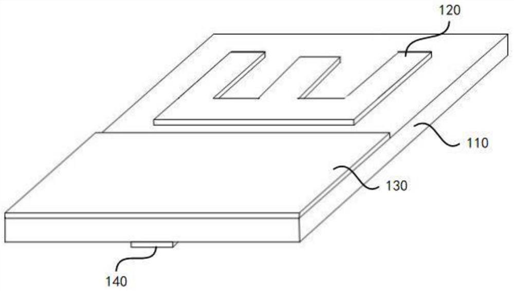
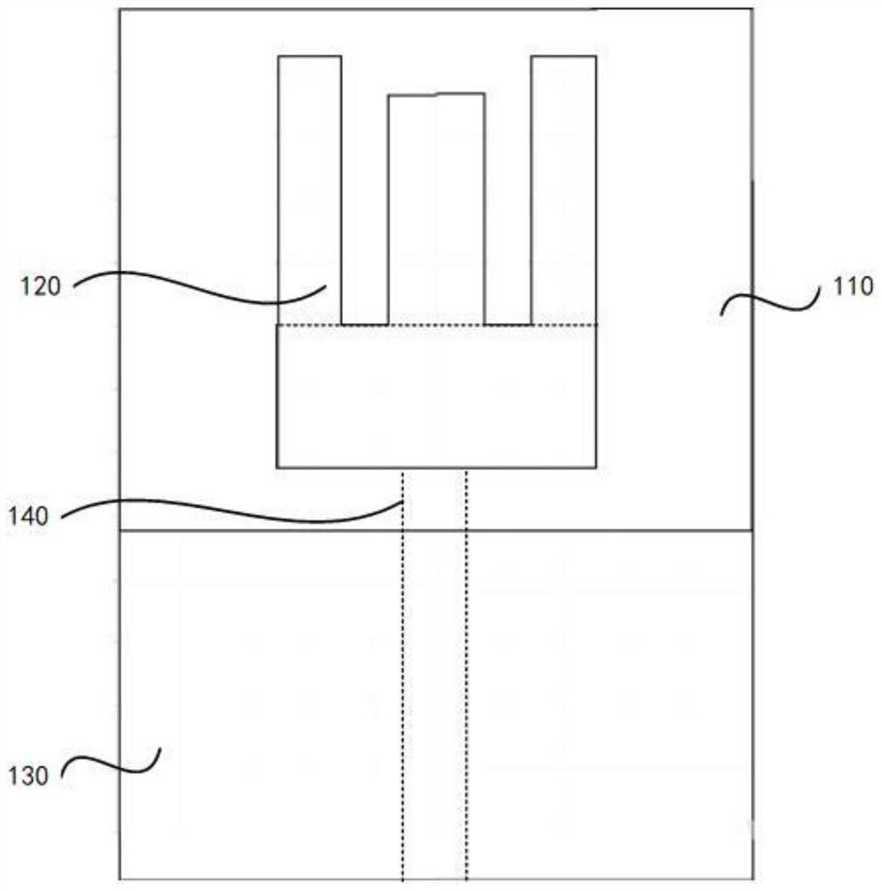
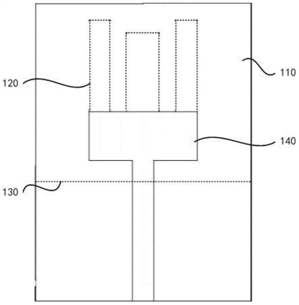
[0043] Specifically, such as Figure 1 to Figure 3 For the microstrip patch antenna shown, the dielectric substrate 110 is a rectangular structure with a width of 20 mm and a height of 32.5 mm, and the ground plate 130 is a rectangular structure with a width of 20 mm and a height of 16 mm, and the ground plate 130 is arranged on the first surface of the dielectric substrate 110 , and the three sides of the ground plate 130 are attached to the three sides of the dielectric substrate 110 respectively, and the radiation patch 120 adopts an E-type radiation patch, wherein the groove bottom is a rectangular structure with a width of 10 mm and a height of 4.5 mm. The two ends of the first side of the groove bottom are respectively provided with a rectangular side groove arm, the width of the side groove arm is 2mm, the height is 8mm, the width of the middle groove arm is 3mm, and the height is 7.3mm. and the middle slot arm, and the two grooves are symmetrical about the center line ...


PUM

PropertyMeasurementUnit
thicknessaaaaaaaaaa
relative permittivityaaaaaaaaaa
dielectric lossaaaaaaaaaa

Abstract

The invention provides a microstrip patch antenna. The microstrip patch antenna comprises a dielectric substrate; the radiation patch is arranged on the first surface of the dielectric substrate; the grounding plate is arranged on the first surface of the dielectric substrate, and a gap is formed between the grounding plate and the radiation patch; and the feed unit is arranged on the second surface of the dielectric substrate, and the feed unit is coupled with the radiation patch. According to the microstrip patch, the antenna impedance bandwidth of the microstrip patch is widened through the radiation patch and the grounding plate which are arranged on the dielectric substrate and the feed unit arranged on the other side of the dielectric substrate.

Description

technical field [0001] The invention belongs to the technical field of communication equipment, and in particular relates to a microstrip patch antenna. Background technique [0002] With the widespread popularization of family cars, the number of vehicles in the road transportation network has increased sharply, the road load has increased, and traffic accidents such as traffic jams, rear-end collisions, and collisions have occurred frequently. The construction of road interchanges and administrative orders have been used to solve traffic congestion problems. With little success. Intelligent Transportation System (Intelligent Transportation System, ITS) emerges in response to this situation, and has a remarkable effect in reducing traffic congestion and reducing the incidence of traffic accidents. The intelligent transportation system includes three parts: information collection system, information processing and analysis system and information release system. Among them, ...

Claims


Application Information

Patent Timeline
Patent Type & Authority Applications(China)
IPC IPC(8): H01Q1/38H01Q1/48H01Q1/50H01Q5/50
CPCH01Q1/38H01Q1/48H01Q1/50H01Q5/50
Inventor 陈亚亮路霞
Owner FAW VOLKSWAGEN AUTOMOTIVE CO LTD
Learn More