
Microgrid operation control device

An operation control and micro-grid technology, applied in the cooling/ventilation of substation/switchgear, substation/switch layout details, electrical components, etc. To achieve the effect of ensuring uniform blowing and cooling effect

Inactive Publication Date: 2022-05-13
HEBEI NORTH UNIV
View PDF3 Cites 0 Cited by
  • Summary
  • Abstract
  • Description
  • Claims
  • Application Information

AI Technical Summary

Problems solved by technology

[0006] The microgrid controller provided by the above scheme cannot effectively dissipate heat inside the controller when it is in use. If the overheating phenomenon of the internal components of the controller is not dealt with in time, it will affect the service life of the components inside the controller. The heat dissipation is affected, and a single-structure fan is used for heat dissipation. The heat dissipation structure is relatively simple, the heat dissipation effect is poor, and the use effect is not ideal.

Method used


Image

  • Microgrid operation control device
  • Microgrid operation control device
  • Microgrid operation control device

Examples


Embodiment 1

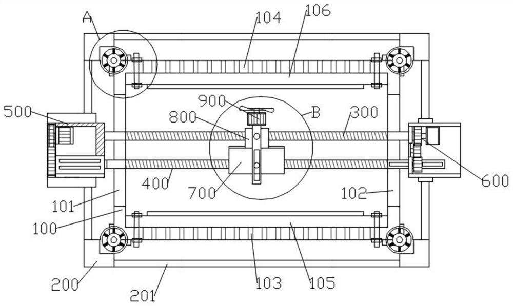
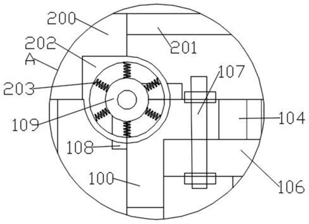
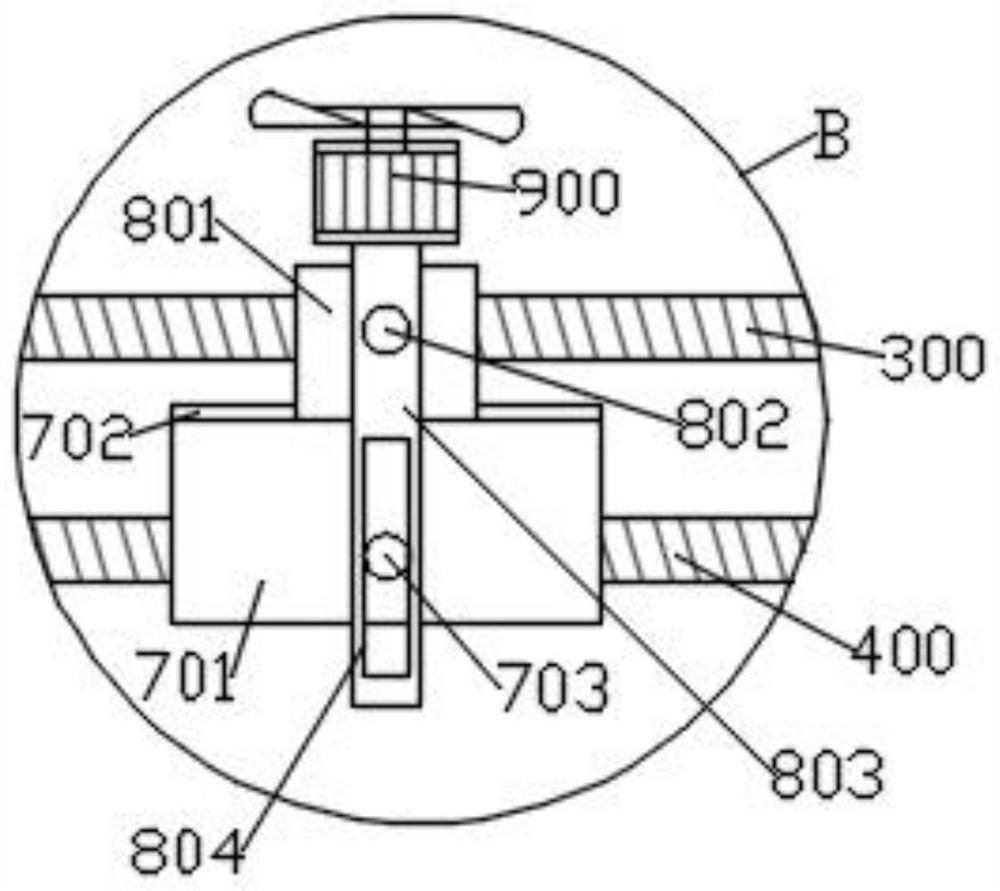
[0039] like Figure 1-2 As shown, in an embodiment provided by the present invention, a microgrid operation control device, the control device includes:

[0040] An adjustment member 500 arranged on one side of the protective shell 200;

[0041] The driver 600 arranged on the other side of the protective shell 200;

[0042] The heat dissipation mechanism located in the box body 100, the position of the heat dissipation mechanism in the box body 100 is adjusted through the screw group, and the screw group is driven by the driving member 600; the screw group includes a structure The same first screw mandrel 300 and second screw mandrel 400, the relative position between the first screw mandrel 300 and the second screw mandrel 400 is adjusted through the adjustment member 500; the heat dissipation mechanism includes a blower 900 , the blower 900 is rotatably installed on the positioning member 800, and the positioning member 800 is installed on the first screw rod 300; Adjustm...

Embodiment 2

[0046] like Figure 1-2 As shown, in an embodiment provided by the present invention, a microgrid operation control device, the control device includes:

[0047] An adjustment member 500 arranged on one side of the protective shell 200;

[0048] The driver 600 arranged on the other side of the protective shell 200;

[0049] The heat dissipation mechanism located in the box body 100, the position of the heat dissipation mechanism in the box body 100 is adjusted through the screw group, and the screw group is driven by the driving member 600; the screw group includes a structure The same first screw mandrel 300 and second screw mandrel 400, the relative position between the first screw mandrel 300 and the second screw mandrel 400 is adjusted through the adjustment member 500; the heat dissipation mechanism includes a blower 900 , the blower 900 is rotatably installed on the positioning member 800, and the positioning member 800 is installed on the first screw rod 300; Adjustm...

Embodiment 3

[0063] like Figure 1-2 As shown, in an embodiment provided by the present invention, a microgrid operation control device, the control device includes:

[0064] An adjustment member 500 arranged on one side of the protective shell 200;

[0065] The driver 600 arranged on the other side of the protective shell 200;

[0066]The heat dissipation mechanism located in the box body 100, the position of the heat dissipation mechanism in the box body 100 is adjusted through the screw group, and the screw group is driven by the driving member 600; the screw group includes a structure The same first screw mandrel 300 and second screw mandrel 400, the relative position between the first screw mandrel 300 and the second screw mandrel 400 is adjusted through the adjustment member 500; the heat dissipation mechanism includes a blower 900 , the blower 900 is rotatably installed on the positioning member 800, and the positioning member 800 is installed on the first screw rod 300; Adjustme...


PUM


Abstract

The invention is suitable for the technical field of micro-grid operation, and provides a micro-grid operation control device, which comprises an adjusting piece arranged on one side of a protective shell; the driving piece is arranged on the other side of the protective shell; the heat dissipation mechanism is located in the box body, the position of the heat dissipation mechanism in the box body is adjusted through a lead screw set, and the lead screw set is driven through the driving piece; the lead screw set comprises a first lead screw and a second lead screw which are the same in structure, and the relative position between the first lead screw and the second lead screw is adjusted through the adjusting piece. The position of the heat dissipation mechanism in the box body is adjusted through the lead screw sets rotating synchronously, relative displacement is generated between the first lead screw and the second lead screw through the adjusting piece, then the direction of the air blower is adjusted, and therefore after the air blower is adjusted to the target position, the direction of the air blower is changed, and the heat dissipation efficiency is improved. The uniformity of blowing of the blower to the target position is improved, and the heat dissipation effect is guaranteed.

Description

technical field [0001] The invention belongs to the technical field of micro-grid operation, and in particular relates to a micro-grid operation control device. Background technique [0002] Microgrid refers to a small power generation and distribution system composed of distributed power sources, energy storage devices, energy conversion devices, loads, monitoring and protection devices, etc. The proposal of microgrid aims to realize the flexible and efficient application of distributed power, and solve the problem of grid connection of distributed power with a large number and various forms. [0003] For example, the patent document with the publication number CN 210536075U discloses a microgrid control device for voltage self-adaptive regulation, including a controller body, and fixing plates are welded on both sides of the controller body, and the fixing plates are Two fixing rods are welded, and the ends of the two fixing rods away from the fixing plate are all welded ...

Claims


Application Information

Patent Timeline
Patent Type & Authority Applications(China)
IPC IPC(8): H02B1/56H02B1/46H02B1/48H02B1/54
CPCH02B1/565H02B1/46H02B1/48H02B1/54
Inventor 韩冰王伟平李俊杰吴婷婷金占双戴彬婷马林郭亚娟
Owner HEBEI NORTH UNIV
Learn More