
Photoelectric module device with anti-falling structure

A photoelectric module, anti-drop technology, applied in the direction of light guide, optics, optical components, etc., can solve the problems that affect the service life of photoelectric modules, do not have anti-drop structure, broken electronic components, etc., and achieve good buffer support effect and structure Compactness and the effect of extending the service life

Inactive Publication Date: 2020-04-17
武汉福地科技有限公司
View PDF8 Cites 0 Cited by
  • Summary
  • Abstract
  • Description
  • Claims
  • Application Information

AI Technical Summary

Problems solved by technology

However, the existing photoelectric module structure is relatively simple, the function is relatively single, and generally does not have an anti-drop structure. When the photoelectric module falls, the internal electronic components are usually broken, which will affect the service life of the photoelectric module. Therefore, we need to design a A photoelectric module device with a drop-proof structure to solve these problems

Method used


Image

  • Photoelectric module device with anti-falling structure
  • Photoelectric module device with anti-falling structure
  • Photoelectric module device with anti-falling structure

Examples


Embodiment 1

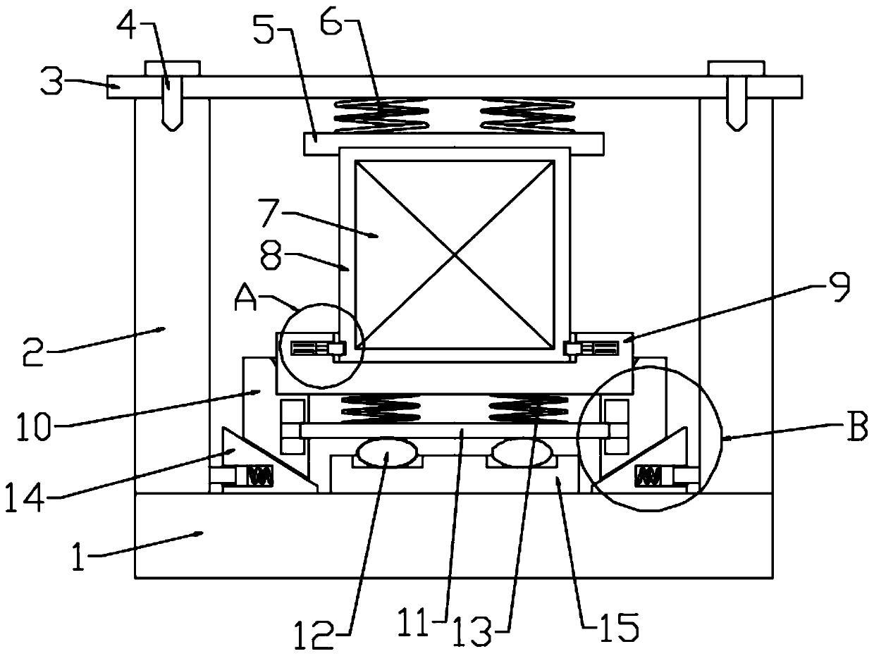
[0033] Such as Figure 1-2 As shown, in the embodiment provided by the present invention, a photoelectric module device with a drop-proof structure includes a photoelectric module body 7, and a protective shell 8 is fixed outside the photoelectric module body 7 to realize the protection of the photoelectric module body. 7 the protective effect carried out;

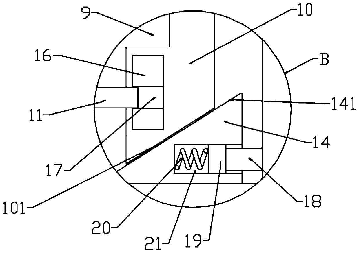
[0034] The protective shell 8 is disassembled and installed on the support base 9; the support base 9 is installed on the base 1 through the erection of the vertical buffer support; Fixed seat 15; the vertical buffer support member also includes a mounting seat 10 supporting the support seat 9, and a guide chute 16 is provided on the mounting seat 10, and the guide chute 16 slides up and down to provide a lift Slider 17; the vertical buffer support also includes a buffer plate 11 fixedly connected to two lift sliders 17 at both ends thereof, and a plurality of vertical buffer plates 11 and the support seat 9 are connected...

Embodiment 2

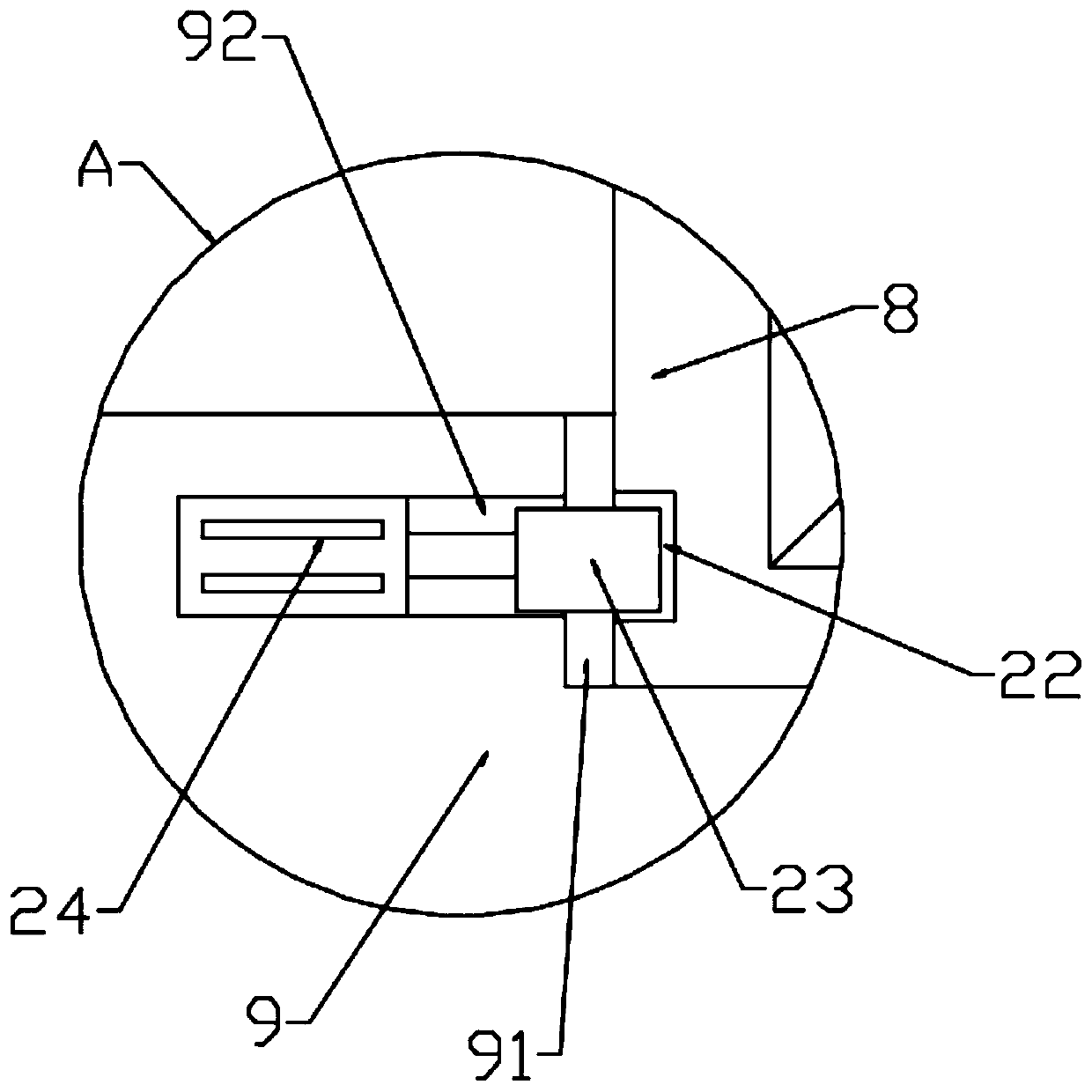
[0041] Such as Figure 1-4 As shown, the difference from Embodiment 1 is that in the embodiment provided by the present invention, a placement groove 91 is opened on the support seat 9, and the protective shell 8 is supported and erected in the placement groove 91, and the The bottom outer wall of the protective shell 8 is provided with a locking groove 22, and the inner wall of the placement groove 91 is provided with a power groove 92, and an electric push rod 24 is fixedly installed in the power groove 92, and the telescopic end of the electric push rod 24 A locking block 23 corresponding to the locking groove 22 is provided;


PUM


Abstract

The invention relates to the technical field of photoelectric modules, and particularly discloses a photoelectric module device with an anti-falling structure, which comprises a photoelectric module body, a protective shell is fixedly wrapped outside the photoelectric module body, the protective shell is detachably installed on a supporting seat, and the supporting seat is erected on a base through a vertical buffer supporting piece. The vertical buffering supporting piece comprises a fixed seat fixedly installed on the base and further comprises an installation seat for supporting the supporting seat, a guide sliding groove is formed in the installation seat, lifting sliding blocks are arranged in the guide sliding groove in an up-down sliding mode, and the vertical buffering supporting piece further comprises a buffering plate with the two ends fixedly connected with the two lifting sliding blocks respectively. The buffering plate and the supporting seat are connected through a plurality of vertical buffer springs in a supporting mode, and a buffer ball is further arranged between the buffering plate and the fixed seat. According to the embodiment of the invention, through mutualcooperation of the buffer ball and the vertical buffer springs, damage caused by accidental collision of the photoelectric module device is effectively avoided.

Description

technical field [0001] The invention relates to the technical field of photoelectric modules, in particular to a photoelectric module device with an anti-drop structure. Background technique [0002] The photoelectric module is a main part of the optical transmission equipment. Its function is photoelectric conversion, that is, first convert the electrical signal into an optical signal, transmit it through the optical fiber, and then convert the transmitted optical signal into an electrical signal through the optical module. However, the existing photoelectric module structure is relatively simple, the function is relatively single, and generally does not have an anti-drop structure. When the photoelectric module falls, the internal electronic components are usually broken, which will affect the service life of the photoelectric module. Therefore, we need to design a A photoelectric module device with a drop-proof structure solves these problems. Contents of the invention ...

Claims


Application Information

Patent Timeline
Patent Type & Authority Applications(China)
IPC IPC(8): G02B6/42F16F15/04
CPCF16F15/04G02B6/4201G02B6/4256G02B6/4257
Inventor 王阳
Owner 武汉福地科技有限公司
Learn More