Waste cable recovery sheath removal device

A sheathing and cable technology, which is applied in the direction of cable installation device, cable installation, dismantling/armouring cable equipment, etc., can solve the problems that the work efficiency of cable peeling cannot be improved, multiple cutting devices are installed, and labor costs are increased. , to achieve the effect of reducing the steps of manual size adjustment, improving practicability and improving work efficiency

Active Publication Date: 2022-05-13
JIANGSU NARI YINLONG CABLE
View PDF11 Cites 0 Cited by
  • Summary
  • Abstract
  • Description
  • Claims
  • Application Information

AI Technical Summary

Problems solved by technology

[0002] In the recycling process of waste cables, it is necessary to cut and remove the outer wall of the cable. During the working process of most of the existing cable peeling machines, the cables of different sizes are cut through holes of different sizes, and then the internal Multiple cutting devices need to be installed, which leads to the problem of high operating power of the equipment. At the same time, after the equipment cuts the cable, it releases the cable and the cable sheath together, which requires manual separation of the cable sheath, which increases labor costs. Improve work efficiency of cable peeling

Method used


Image

  • Waste cable recovery sheath removal device
  • Waste cable recovery sheath removal device
  • Waste cable recovery sheath removal device

Examples


Embodiment 1

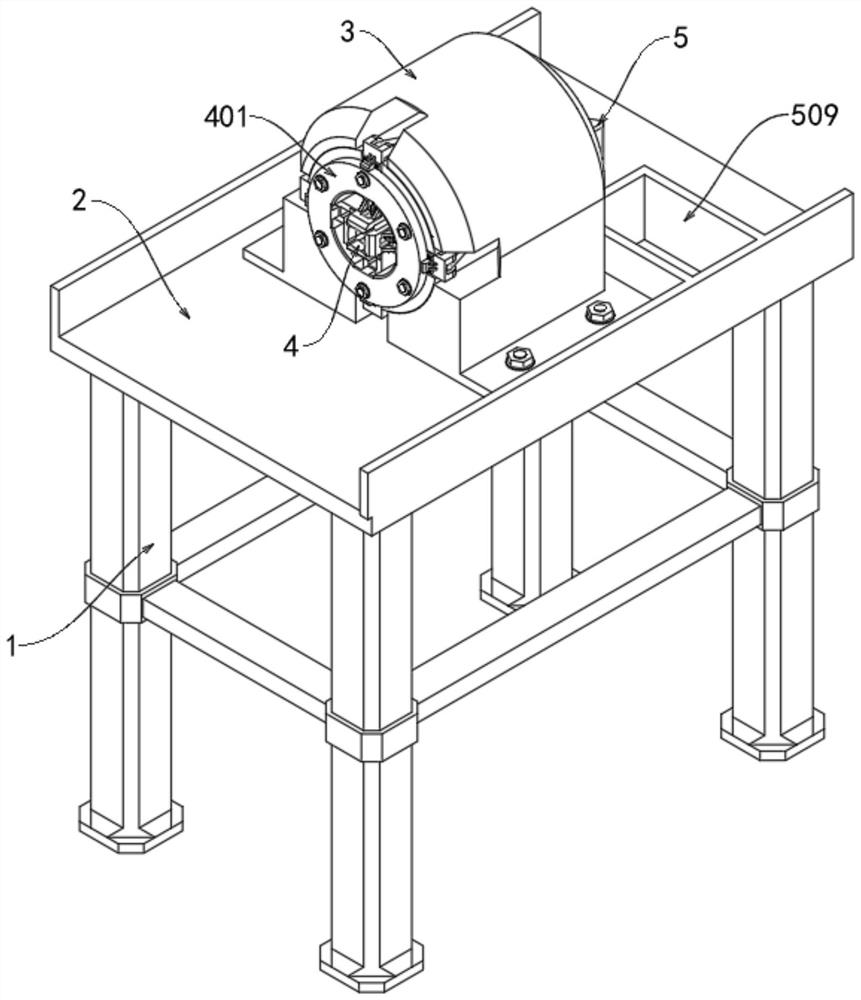
[0032] Please refer to Figure 1 to Figure 3 As shown, a waste cable recovery sheath removal device includes a support frame 1, the inner upper end of the support frame 1 is fixedly connected with a workbench 2, the upper surface of the workbench 2 is fixedly connected with a fixed base 3, and the inside of the fixed base 3 is fixed The adapter mechanism 4 is connected, and the inside of the adapter mechanism 4 is provided with a collection mechanism 5 .

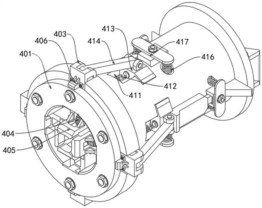
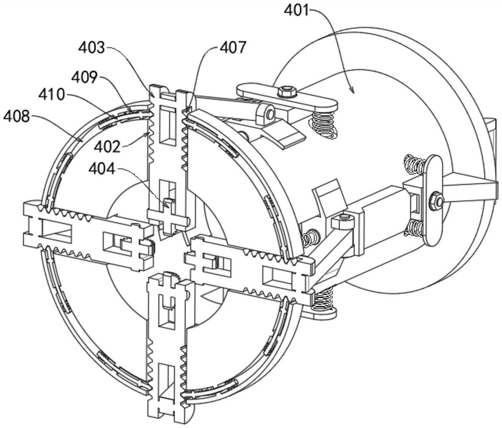
[0033] The adapter mechanism 4 includes a working base 401, a first movable port 402, an adapter block 403, a rolling tooth 404, a scraper 405 and a limit block 406. The inside of the fixed base 3 is fixedly connected with the working base 401, and the inside of the working base 401 There is a first movable port 402, and the inside of the first movable port 402 is movably connected with an adapter block 403, and the inner side of the adapter block 403 and close to the inner part of the working base 401 is rotatably connected...

Embodiment 2

[0038] Please refer to figure 2 and Figure 4 As shown, the adapter mechanism 4 also includes a chute 411, a second spring 412, a slider 413, a connecting rod 414, a second movable port 415, a third spring 416, a motor 417 and a peeling wheel 418, and the outer wall of the working base 401 A chute 411 is penetrated, the inner wall of the chute 411 is fixedly connected to one end of the second spring 412, the other end of the second spring 412 is fixedly connected to the inside of the chute 411 with a slider 413, and the inner side of the slider 413 is provided with The incline inclined at 45 degrees plays a role in pushing the motor 417 to move inward. The slider 413 moves inside the chute 411. The outer side of the slider 413 is rotationally connected with one end of the connecting rod 414, and the other end of the connecting rod 414 Rotately connected with the outside of the adapter block 403, the outer wall of the working base 401 is penetrated with a second movable openi...

Embodiment 3

[0041] Please refer to figure 1 , Figure 5 and Figure 6 As shown, the collection mechanism 5 includes a third movable port 501, a connecting plate 502, a push block 503, a fourth spring 504, a movable block 505, a push port 506, a collection scraper 507, a collection guide plate 508 and a collection port 509, and the working base The outer wall of 401 is provided with a third movable opening 501, the outer side of the slider 413 is fixedly connected with a connecting plate 502, and the outer side of the connecting plate 502 is fixedly connected with a push block 503, and the outer side of the push block 503 is provided with a slope inclined at 45 degrees. The movable block 505 can be driven to move outward under the action of the inclined surface of the push block 503, the outer wall of the working base 401 is fixedly connected with the fourth spring 504, and the outer side of the fourth spring 504 and the inside close to the third movable port 501 are fixedly connected wit...


PUM


Abstract

The invention discloses a waste cable recovery sheath removing device which comprises a supporting frame, a workbench is fixedly connected to the upper end of the interior of the supporting frame, a fixed base body is fixedly connected to the upper surface of the workbench, an adaptive mechanism is fixedly connected to the interior of the fixed base body, and a collecting mechanism is arranged on the inner side of the adaptive mechanism. The device comprises a fixed base body, a working base body is fixedly connected to the interior of the fixed base body, a first movable opening is formed in the working base body, and an adaptive block is movably connected to the interior of the first movable opening. And under the action of the cable, the rolling teeth drive the adaptive block to move towards the outer side in the first movable opening, so that the function of automatically adapting to the cables with different sizes is realized, the step of manually adjusting the size is reduced, the application range of the equipment is widened, the practicability of the equipment is effectively improved, and the practicability of the equipment is improved. And meanwhile, the working efficiency of cable peeling of the equipment is improved.

Description

technical field [0001] The invention relates to the technical field of cable recovery, in particular to a device for removing the sheath of waste cable recovery. Background technique [0002] In the recycling process of waste cables, it is necessary to cut and remove the outer wall of the cable. During the working process of most of the existing cable peeling machines, the cables of different sizes are cut through holes of different sizes, and then the internal Multiple cutting devices need to be installed, which leads to the problem of high operating power of the equipment. At the same time, after the equipment cuts the cable, it releases the cable and the cable sheath together, which requires manual separation of the cable sheath, which increases labor costs. Improve the work efficiency of cable peeling. [0003] For this reason, a kind of discarded cable reclaiming sheath removal device is proposed. Contents of the invention [0004] The object of the present inventio...

Claims


Application Information

Patent Timeline
Patent Type & Authority Applications(China)
IPC IPC(8): H02G1/12H01B15/00
CPCH02G1/126H01B15/006Y02W30/82
Inventor 曹点点王中建李朝峰赵士银李建新
Owner JIANGSU NARI YINLONG CABLE
Why Eureka
Try Eureka