Light source control method and device, electronic equipment and computer readable storage medium

A control method and technology of electronic equipment, applied in the field of communication, can solve problems such as crosstalk and unstable signal transmission, and achieve the effect of solving signal crosstalk

Pending Publication Date: 2022-05-13
SHENZHEN LUMIUNITED TECH CO LTD
View PDF0 Cites 0 Cited by
  • Summary
  • Abstract
  • Description
  • Claims
  • Application Information

AI Technical Summary

Problems solved by technology

[0005] In the process of implementing the embodiments of the present application, the inventors found at least the following problems in the above related technologies: At present, due to the development of optical communication technology, the light source has the functions of supplementary light and data transmission at the same time, but in actual use, usually only use One of the functions of the light source is to produce electronic equipment. This is because when the two functions are realized at the same time, crosstalk is likely to occur between the switching signal of the light source and the transmitted data signal, resulting in unstable signal transmission.

Method used


Image

  • Light source control method and device, electronic equipment and computer readable storage medium
  • Light source control method and device, electronic equipment and computer readable storage medium
  • Light source control method and device, electronic equipment and computer readable storage medium

Examples


Embodiment 1

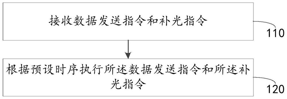
[0053] The embodiment of this application provides a light source control method, please refer to image 3 , which shows the flow of a light source control method provided by the embodiment of the present application, the method includes but not limited to the following steps:

[0054] Step 110: receiving a data sending instruction and a supplementary light instruction;

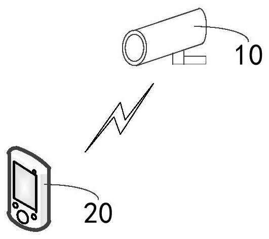
[0055] The light source control method provided by the embodiment of the present application can be applied to the monitoring camera 10 described in the above application scenarios, or to other electronic devices that require supplementary light to work normally in specific scenarios, and can be implemented according to actual needs. set up. Before executing the control method provided by the embodiment of the present application to control the power supply, firstly, it is necessary to obtain a data sending instruction and a supplementary light instruction.

[0056] Wherein, the data sending instruction may...

Embodiment 2

[0095] The embodiment of this application provides a light source control device, please refer to Figure 12 , which shows a control device for a light source provided in an embodiment of the present application, the device 200 includes:

[0096] a receiving unit 210, configured to receive a data sending instruction and a supplementary light instruction;

[0097] The execution unit 220 is configured to execute the data sending instruction and the supplementary light instruction according to a preset timing.

[0098] In some examples, see Figure 13 , which shows another light source control device provided by the embodiment of the present application, the device 200 also includes:

[0099] The judging unit 230 is configured to judge whether the data sending instruction and the supplementary light instruction need to be executed simultaneously.

[0100] In some embodiments, the number of the light source is one;

[0101] The executing unit 220 is further configured to first...

Embodiment 3

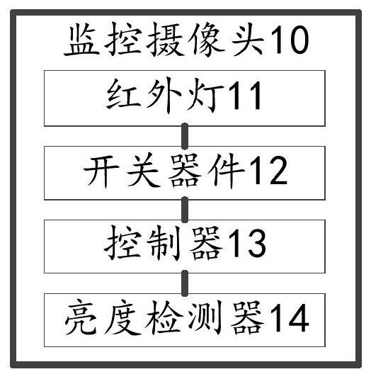
[0109] The embodiment of the present application also provides an electronic device, please refer to Figure 14 , which shows the ability to execute Figure 3 to Figure 11 The hardware structure of the electronic equipment of the light source control method. The electronic device 10 may be figure 1 The surveillance camera 10 shown may also be other electronic devices that need to supplement light and send data in specific scenarios. The electronic device 10 includes: at least one light source 11 ; a switch device 12 connected to the light source 11 ; and a controller 13 connected to the switch device 12 . The controller 13 can control the switching device 12 in time sequence, so that the at least one light source 11 can execute a supplementary light instruction and a data sending instruction. Further, see Figure 15 , which shows the hardware structure of another electronic device, the electronic device 10 may further include: a brightness detector 14 connected to the cont...


PUM


Abstract

The embodiment of the invention relates to the technical field of communication, and discloses a light source control method and device, electronic equipment and a computer readable storage medium, and the method comprises the steps: firstly receiving a data sending instruction and a light supplementing instruction, and then executing the data sending instruction and the light supplementing instruction according to a preset time sequence; according to the light source control method provided by the embodiment of the invention, the light source is controlled to execute the light supplementing instruction and the data sending instruction, so that the problem of signal crosstalk can be solved.

Description

technical field [0001] The embodiments of the present application relate to the field of communication technologies, and in particular, to a method, device and electronic equipment for controlling a light source. Background technique [0002] Optical communication uses light waves as the transmission medium. According to whether the human eye is visible or the length of the wavelength can be divided into visible light communication and invisible light communication, and the transmission medium can be divided into wired optical communication and wireless optical communication (atmospheric optical communication) At present, wireless optical communication is favored by manufacturers and markets in the field of communication due to its advantages such as no need to lay lines, light equipment, easy maneuverability, good confidentiality, and large amount of transmitted information. Wireless optical communication technology is also constantly developing. and progress. [0003] Amo...

Claims


Application Information

Patent Timeline
IPC IPC(8): H04N5/235H04N7/18H04N5/33H04B10/11H04B10/50
CPCH04N7/18H04N5/33H04B10/11H04B10/501H04N23/71H04N23/74
Inventor 柏文权
Owner SHENZHEN LUMIUNITED TECH CO LTD
Why Eureka
Try Eureka