
A touch pad alignment device

An alignment device and touchpad technology, applied in the direction of assembling printed circuits, printed circuits, electrical components, etc. with electrical components, which can solve the problems of easily damaged touchpads and low adaptability, achieve rapid positioning, and reduce contact area. , the effect of reducing friction

Active Publication Date: 2022-06-21
深圳凯升联合科技有限公司
View PDF7 Cites 0 Cited by
  • Summary
  • Abstract
  • Description
  • Claims
  • Application Information

AI Technical Summary

Problems solved by technology

[0004] The purpose of the present invention is to solve the problem that there is a hard contact between the clamp and the touch panel of the traditional alignment device in the prior art. When the touch panel is clamped and fixed, the touch panel is easily damaged, and the touch panel of different sizes is aligned. Position, the disadvantage of low adaptability, and proposed a touch pad alignment device

Method used


Image

  • A touch pad alignment device
  • A touch pad alignment device
  • A touch pad alignment device

Examples


Embodiment 1

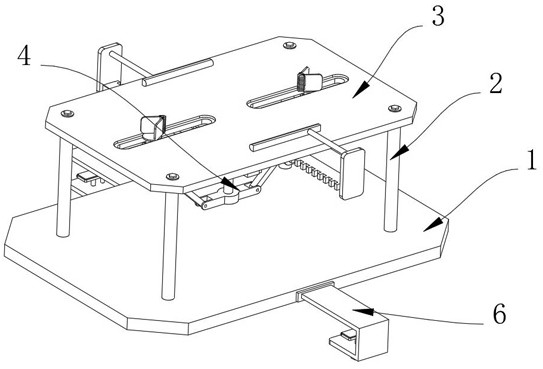
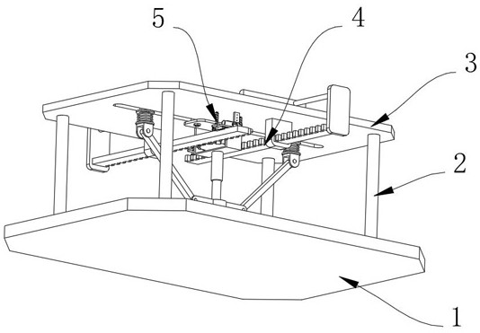
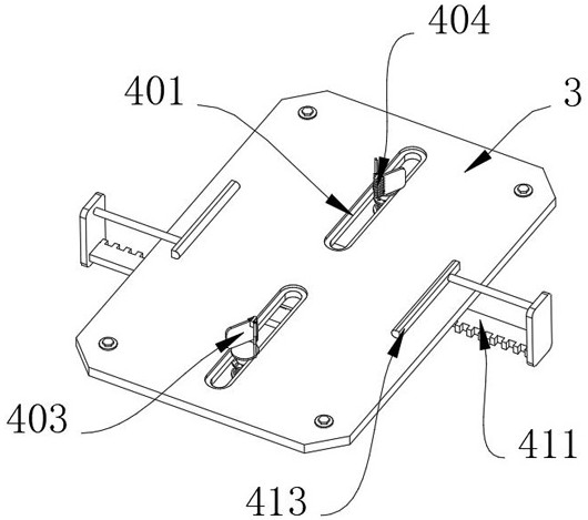
[0043] Example 1, as Figure 1-8 As shown, the present invention provides a touchpad fitting and alignment device, which includes a backing plate 1 and a positioning structure 4. The four corners of the upper surface of the backing plate 1 are fixedly connected with support rods 2, and the upper ends of the four support rods 2 are fixedly connected. There is a positioning plate 3 , a positioning structure 4 is arranged on the surface of the positioning plate 3 , a lubricating structure 5 is arranged at the position of the positioning plate 3 corresponding to the rack 411 , and a limiting structure 6 is arranged on both sides of the backing plate 1 .

[0044] The specific settings and functions of the positioning structure 4 , the lubricating structure 5 and the limiting structure 6 will be described in detail below.

[0045] like Figure 4 and Figure 5 As shown, the positioning structure 4 includes two sliding holes 401, both of which are opened on the surface of the positi...

Embodiment 2

[0049] Embodiment 2, on the basis of embodiment 1, as figure 1 and Figure 8 As shown, the limiting structure 6 includes a mounting block 61, the mounting block 61 is welded on the surface of the backing plate 1, the side of the mounting block 61 away from the backing plate 1 is fixedly connected to the limiting frame 62, and the short arm end of the limiting frame 62 is threadedly inserted There is a screw 63, the upper end of the screw 63 is rotatably connected with a pressure plate 64, and the upper surface of the pressure plate 64 is fixedly connected with a silicone pad 65, so as to achieve the effect that the pad 1 can be quickly installed on the touch panel processing equipment by means of the screw 63 and the pressure plate 64. A sliding rod 66 is fixedly connected to the side of the pressing plate 64 close to the screw 63 , and the lower end of the sliding rod 66 slides through the limiting frame 62 , so as to limit the moving position of the pressing plate 64 .

[0...


PUM


Abstract

The invention provides a touchpad lamination and alignment device, which relates to the technical field of touchpad lamination and alignment devices, and includes a backing plate and a positioning structure. The four corners of the top surface of the backing plate are fixedly connected with support rods, and the four The upper end of the support rod is fixedly connected with a positioning plate, and the surface of the positioning plate is provided with a positioning structure, and the positioning structure includes two sliding holes, and the two sliding holes are all opened on the surface of the positioning plate, and the positioning structure is provided on the surface of the positioning plate. The inner wall of the sliding hole is slidably connected with a slider, the cross section of the slider is in the shape of "I", the upper end of the slider is fixedly connected with a positioning piece, the tip of the positioning piece is clamped with a rubber piece, and the The lower end is rotatably connected with a rotating plate. The present invention solves the problem of the hard contact between the clamping part and the touch panel of the traditional alignment device, which is easy to damage the touch panel when clamping and fixing the touch panel, and the adaptability is poor when aligning touch panels of different sizes. low problem.

Description

technical field [0001] The present invention relates to the technical field of touchpad bonding and alignment devices, in particular to a touchpad bonding alignment device. Background technique [0002] The touchpad fitting and alignment device refers to a device in which the auxiliary processing machinery quickly aligns the touchpad parts with the originals such as circuit boards and then installs them during the manufacturing process of some electronic devices with touchpads. [0003] In the field of circuit printing, the traditional alignment device generally clamps and fixes the touch panel to achieve the effect of auxiliary alignment, while the clamp of the traditional alignment device is in hard contact with the touch panel. , it is easy to damage the touchpad, and when aligning touchpads of different sizes, the adaptability is low. SUMMARY OF THE INVENTION [0004] The purpose of the present invention is to solve the problem that in the prior art, there is a hard c...

Claims


Application Information

Patent Timeline
Patent Type & Authority Patents(China)
IPC IPC(8): H05K3/30H05K13/04
CPCH05K3/30H05K13/0404H05K13/0406H05K2203/167
Inventor 杨培桢
Owner 深圳凯升联合科技有限公司
Learn More