Device arranged on press machine and used for forging wind power flange blank making and punching

A flanged and press technology, applied in the field of punching devices, can solve problems such as dangers in manual operation, and achieve the effect of improving work efficiency

Active Publication Date: 2022-05-17
SHANXI TIANBAO GRP CO LTD
View PDF13 Cites 0 Cited by
  • Summary
  • Abstract
  • Description
  • Claims
  • Application Information

AI Technical Summary

Problems solved by technology

[0005] In order to overcome the disadvantage that the existing punching device needs to manually adjust the position of the workpiece, and manual operation is prone to danger, the technical problem of the present invention is: to provide a device that can automatically adjust the position of the flange, thereby improving safety. A device for punching blanks for forging wind power flanges on a press

Method used


Image

  • Device arranged on press machine and used for forging wind power flange blank making and punching
  • Device arranged on press machine and used for forging wind power flange blank making and punching
  • Device arranged on press machine and used for forging wind power flange blank making and punching

Examples


Embodiment 1

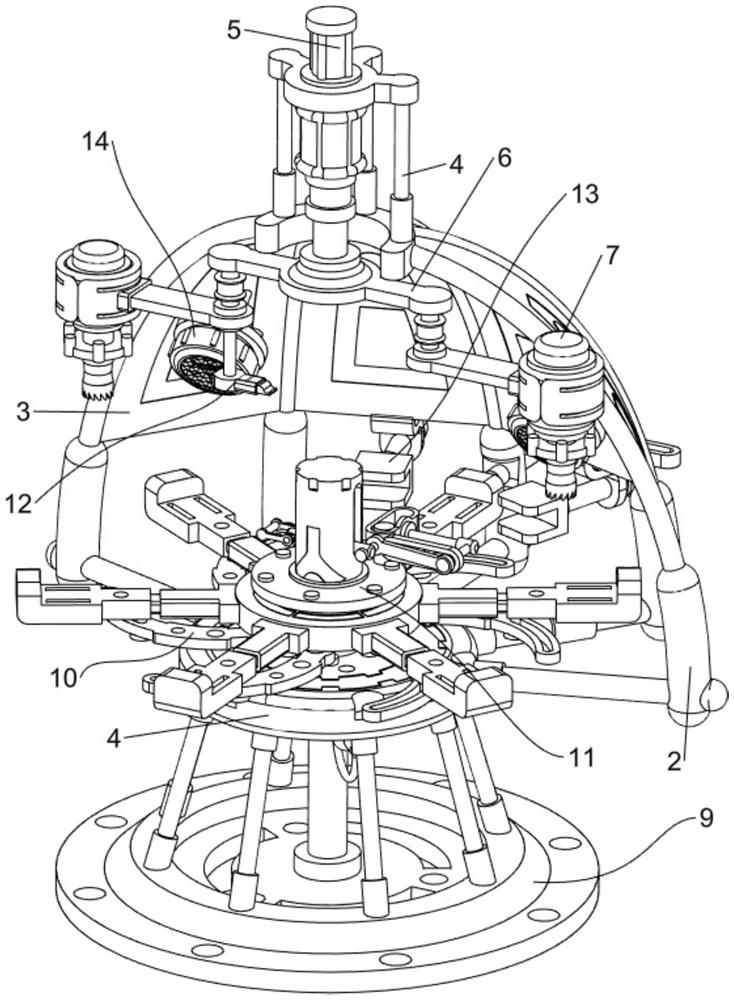
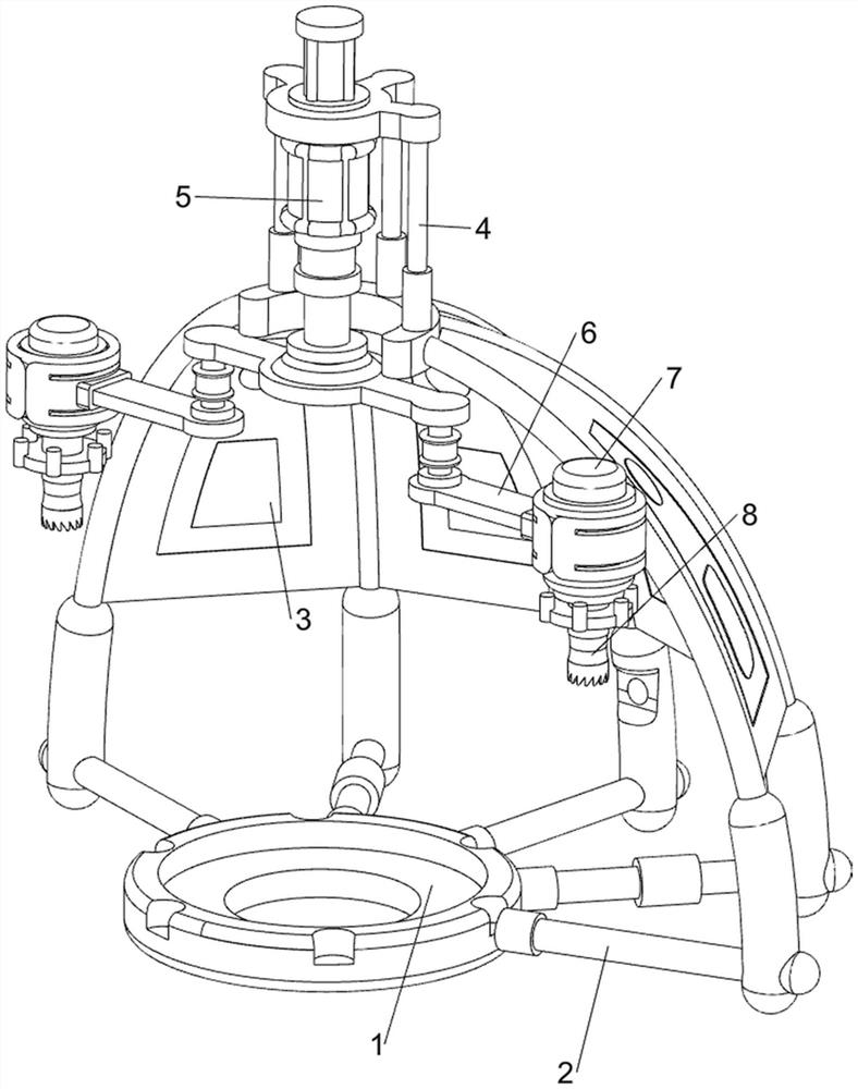
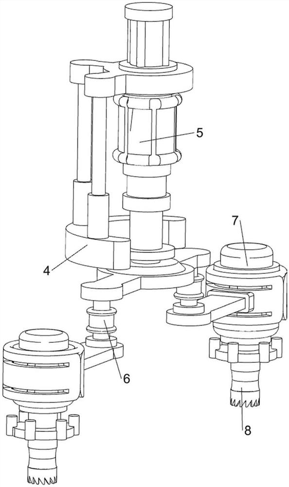
[0040] A device configured to forge wind power flange blank punching on a press, in Figure 1- Figure 3Shown in, including a support block 1, protective frame 2, protective plate 3, support frame 4, electric pushrod 5, lifting frame 6, servo motor 7, punching block 8, rotating mechanism 9, clamping mechanism 10, transmission mechanism 11 and dialing mechanism 12, support block 1 is provided with a protective frame 2 on the rear outer side, support block 1 is provided with a counterweight block at the bottom, which can increase the weight of support block 1, thereby reducing the possibility of dumping of the device, the protective frame 2 is evenly connected to four protective plates for blocking debris 3, The top of the protective frame 2 is connected to the support frame 4 by means of screw connection, the support frame 4 is connected to the top of the four guard plates 3, the support frame 4 is installed with an electric pushrod 5, the telescopic rod of the electric pusher 5 is ...

Embodiment 2

[0047] On the basis of Example 1, on Figure 1 、 Figure 14 and Figure 15 Shown in the middle, further comprising a loose release mechanism 13, the loose release mechanism 13 includes a second connecting block 130, a cotton block 131, a connection spring 132, a guide rod 133, a T-bar 134 and a push block 135, the middle two protective plates 3 are connected to the bottom of the second connection block 130, the two second connection block 130 are provided with a cotton block capable of limiting the flange 131, two cotton blocks 131 and the same side of the second connection block 130 rear are connected to the connection spring for reset 132, The lower middle sliding type of the protective frame 2 is provided with a guide rod 133, the slider 95 is in contact with the guide rod 133, the rear of the guide rod 133 is provided with a T-rod 134, the T-rod 134 is symmetrically provided with a push block 135, and the two push blocks 135 are connected to the back side sliding type of the cot...


PUM


Abstract

The invention relates to a punching device, in particular to a punching device for forging a wind power flange blank on a press machine. According to the device arranged on the press machine and used for forging the wind power flange blank and punching, the position of the flange plate can be automatically adjusted, and then safety is improved. A device arranged on a press machine and used for forging wind power flange blank making and punching comprises a supporting block, a protection frame, protection plates, a supporting frame and the like, the protection frame is arranged on the outer side of the rear portion of the supporting block, the four protection plates are evenly connected to the protection frame, the supporting frame is arranged on the top of the protection frame, and the supporting frame is connected with the tops of the four protection plates. After two through holes are punched in the flange plate, the lifting frame resets to enable the shifting mechanism to work to drive the sliding block to rotate through the transmission mechanism, then the flange plate is driven to rotate by one sixth, the purpose of automatic adjustment can be achieved, the position of the flange plate does not need to be manually adjusted, and safety is higher.

Description

Technical field [0001] The present invention relates to a punching apparatus, in particular to a device configured to forge wind power flange blank punching on a press. Background [0002] Wind power flanges are structural parts that connect the various segments of the tower or the tower and the hub, the hub and the blade, usually using bolting. At the hub joint, it is necessary to use a device to open a hole in the ring of the edge of the flange disc to facilitate the installation of bolts, and then connect the various sections of the tower, and these through holes are generally made by punching or drilling. [0003] Publication number CN212551262U of a flange punching device, comprising a frame, punching mechanism, support turntable and clamping mechanism; the clamping mechanism comprises a drive cylinder, a stroke taper core, a tension taper disc and a reset spring; the tension taper disc is a ring structure composed of a plurality of taper discs, and the center of the tensio...

Claims


Application Information

Patent Timeline
Patent Type & Authority Applications(China)
IPC IPC(8): B21J9/04B21J13/00B21J13/10B08B1/00B08B1/02B08B5/02
CPCB21J9/04B21J13/00B21J13/10B08B1/006B08B1/02B08B5/02B21D28/30B23Q39/023Y02E10/72
Inventor 胡大为闫志龙刘俊杰乔勇强石少华赵延军张雁玲
Owner SHANXI TIANBAO GRP CO LTD
Why Eureka
Try Eureka