Seat leg support mechanism and seat
A technology of seat legs and seat frame, which is applied to vehicle seats, special positions of vehicles, vehicle components, etc., and can solve problems such as unsmooth adjustment
- Summary
- Abstract
- Description
- Claims
- Application Information
AI Technical Summary
Problems solved by technology
Method used
Image

Examples
Embodiment 2
[0049] In addition, a variety of driving methods are provided to realize the manual function.
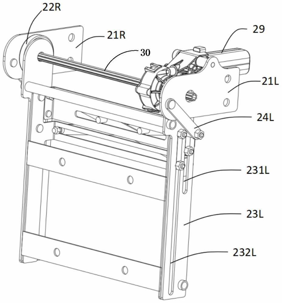
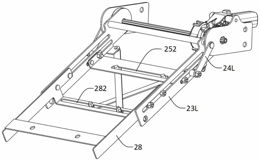
[0050] The difference from Embodiment 1 is that the intermediate link 30 is provided with a rotating part, and the rotating part is exposed to the outside through the hinge and the fixed bracket, and the intermediate link can be driven by manual drive components such as a crank handle installed on the intermediate link 30. The forward and reverse rotation of the rod 30 can realize the opening and retraction of the leg rest mechanism 2 . Preferably, the intermediate connecting rod 30 is a spline shaft structure, the spline shaft is matched with the hinge, and the crank handle is provided with a spline groove, so the end of the crank handle and the intermediate connecting rod 30 can be assembled to drive the intermediate connecting rod 30 to rotate. Realize the opening and retracting of the leg rest mechanism 2. As a result, manual functions have been further added to provide car com...
Embodiment 3
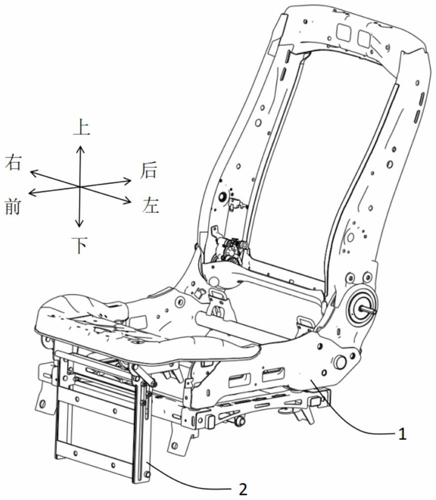
[0052] Also disclosed is a car seat, including the leg support mechanism 2 in the first embodiment and the second embodiment; thus, the car seat has a leg support function.
PUM
 Abstract
Description
Claims
Application Information
PatSnap Eureka turns technology decisions into work you can execute. Powered by our Innovation Knowledge Graph, it runs expert workflows across engineering, life sciences, materials and intellectual property. Get your review-ready output in minutes.


