Kit for detecting tuberculosis bacteria
A technology of kits and germs, applied in the field of kits, can solve the problems of potential safety hazards, reagents falling to the ground, and excessive force to extract them, so as to avoid falling damage and conveniently take the tuberculosis reagents
- Summary
- Abstract
- Description
- Claims
- Application Information
AI Technical Summary
Problems solved by technology
Method used
Image

Examples
Embodiment
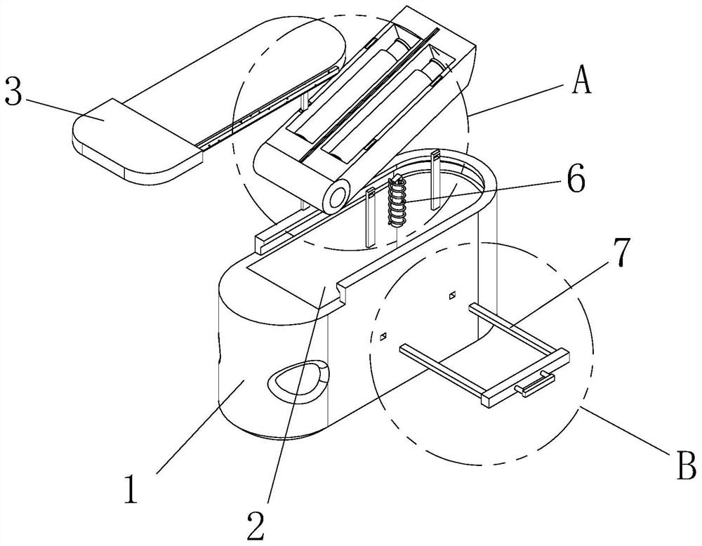
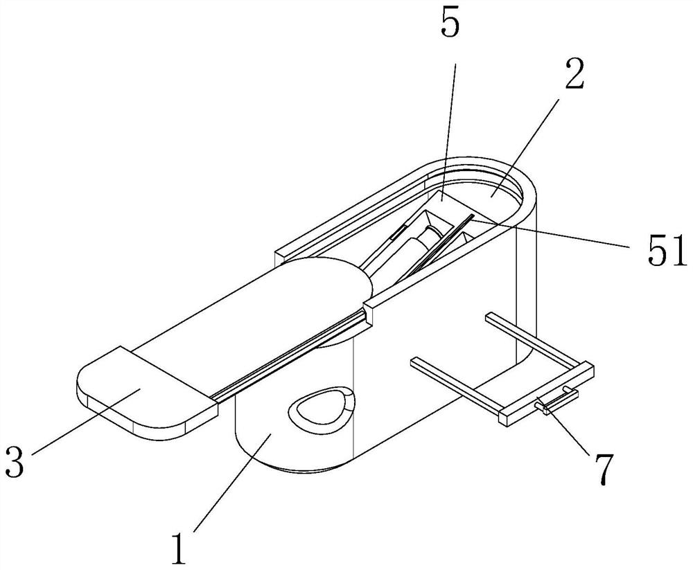
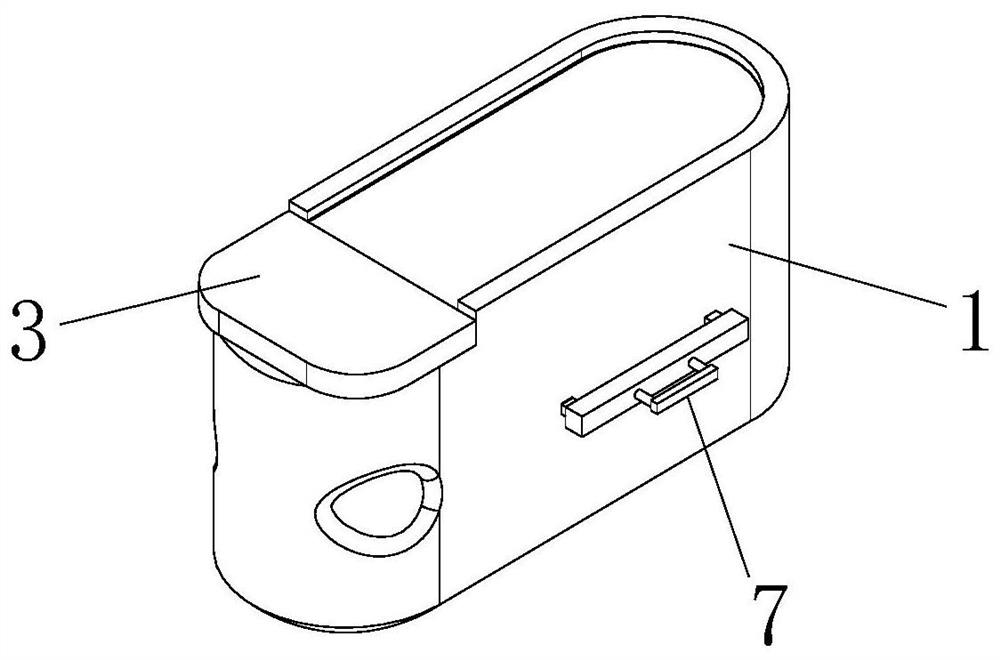
[0030] Such as figure 1 - Figure 9 As shown, a kit for testing tuberculosis bacteria includes a kit body 1, a kit cavity 2 is provided in the kit body 1, and the bottom of the kit cavity 2 is rotatably connected to a tuberculosis reagent 4. Place chamber 5. Concretely, place one end of cavity 5 (such as figure 1 The left end shown) is provided with a shaft hole, and the empty sleeve in the shaft hole is plugged with a rotating shaft, and the two ends of the rotating shaft are snapped and fixed on the inner walls of both sides of the reagent box cavity 2, so that the placement cavity 5 can be placed in the reagent box cavity 2 It rotates within a certain angle range around the rotating shaft.
[0031] The bottom of the placement cavity 5 is slidably connected with a take-out component 6 fixedly connected to the bottom surface of the reagent box cavity 2 . Such as Figure 4 to Figure 6 and Figure 8 As shown, the take-out assembly 6 includes a telescopic rod 61 fixed on t...
PUM
 Abstract
Description
Claims
Application Information