LA-ICP-MS dynamic deformation beam spot test method and device

A LA-ICP-MS, dynamic deformation technology, applied in the preparation of test samples, measurement devices, instruments, etc., can solve the problems of not meeting the test technical requirements, unable to achieve laser beam spot deformation, etc., to save samples, reduce The effect of mixing impurities and improving accuracy

Pending Publication Date: 2022-05-17
INST OF GEOCHEM CHINESE ACADEMY OF SCI
View PDF0 Cites 0 Cited by
  • Summary
  • Abstract
  • Description
  • Claims
  • Application Information

AI Technical Summary

Problems solved by technology

Because it is known that the pulse laser of LA-ICP-MS will change the surface morphology and defocus of the sample every time, and when the sample is a geological sample, only adjusting the vertical distance of the cladding head to change the defocus will still make the non-focus in the beam spot The target particles are ablated, these calculations, adjustment steps are time consuming for the adjustment of the laser beam
[0004] It is also disclosed in the prior art that the filter hole described in the laser beam space shaping device is located at the focus of the confocal system (maximum energy density). - The laser beam spot deformation in the ablation energy range of ICP-MS does not meet the testing technical requirements of LA-ICP-MS

Method used


Image

  • LA-ICP-MS dynamic deformation beam spot test method and device
  • LA-ICP-MS dynamic deformation beam spot test method and device
  • LA-ICP-MS dynamic deformation beam spot test method and device

Examples


Embodiment 1

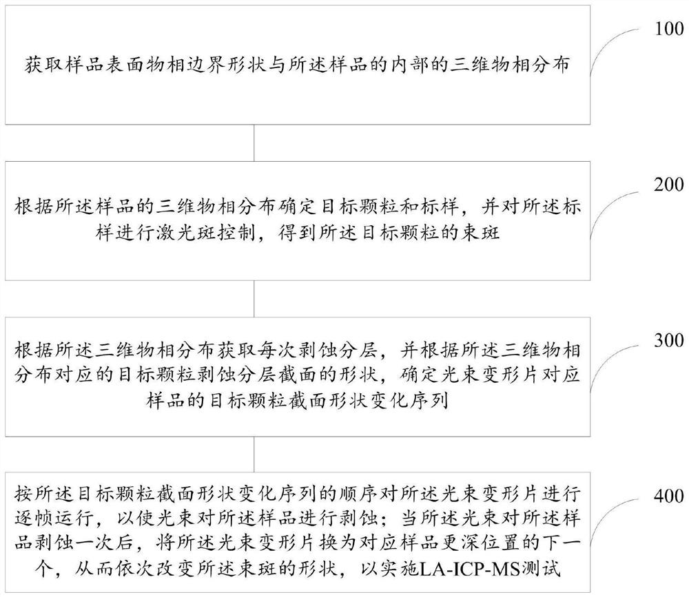
[0046] figure 1 The method flowchart in the embodiment 1 that the present invention provides, such as figure 1 As shown, the present invention provides a kind of testing method of LA-ICP-MS dynamic deformation beam spot, comprising:

[0047] Step 100: Obtain the phase boundary shape on the surface of the sample and the three-dimensional phase distribution inside the sample;

[0048] Step 200: Determine the target particle and the standard sample according to the three-dimensional phase distribution of the sample, and perform laser spot control on the standard sample to obtain the beam spot of the target particle;

[0049] Step 300 Obtain each ablation layer according to the three-dimensional phase distribution, and determine the shape change sequence of the cross-sectional shape of the target particle corresponding to the beam deformation sheet according to the shape of the ablation layer section of the target particle corresponding to the three-dimensional phase distribution...

Embodiment 2

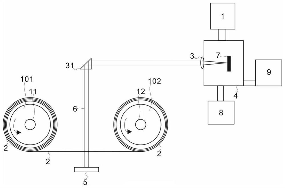
[0058] figure 2 The structural schematic diagram in the embodiment 2 that the present invention provides, as figure 2 As shown, the LA-ICP-MS equipment with dynamic deformation beam spot includes: mass spectrometer module 1, beam deformation plate 2, lens module 3, sample chamber 4, laser module 5, carrier gas module 8, vacuum module 9; beam deformation Sheet 2 is more than one film generated according to the three-dimensional layered structure of the sample 7; the pipeline of the sample chamber 4 is connected to the mass spectrometer module 1, the carrier gas module 8, and the vacuum module 9; the laser module 5 emits a light beam 6; when the sample chamber 4 When vacuumed by the vacuum module 9 and the sample 7 is detachably fixed, the beam 6 at least passes through the lens module 3 and the beam deformation plate 2 to form a beam spot 61 to ablate the sample 7, and the beam 6 can also be a parallel beam or a beam of non-ablative energy range A prism module 31 is added, a...

Embodiment 3

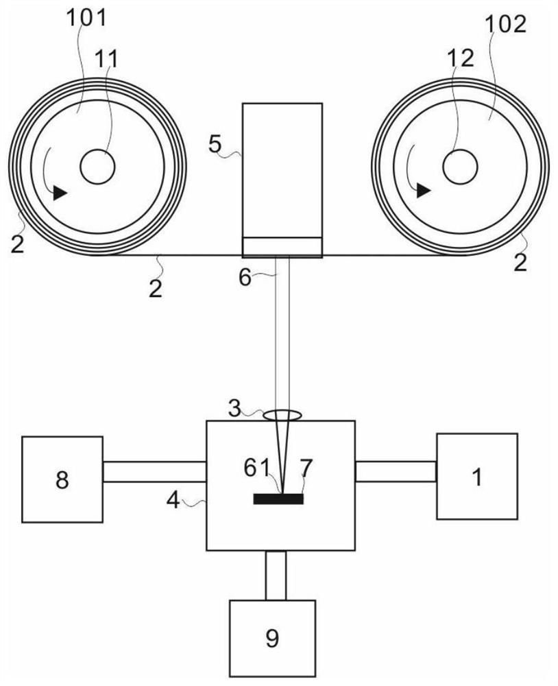
[0060] image 3 The structural representation in the embodiment 3 provided for the present invention, such as image 3 As shown, compared with the above, the beam deforming sheet 2 of Example 3 is a sheet-like excitation source arranged in a strip shape, which directly changes the shape of the excitation source, thereby changing the shape of the light source. The shape of the beam spot 61 can be constrained by changes in the shape of the light source at a distance greater than twice the focal length of the convex lens of the lens module by known techniques. At this time, the beam deforming sheet 2 passes through the laser module 5 in one direction. When the beam deforming sheet 2 passes through, the position of the beam 6 emitted by the laser module 5 is attached but not fixed to change the shape of the beam 6 . The first stepping motor 11 drives the first rotating wheel 101, and the beam deformation sheet 2 that has not passed the laser module 5 is wound and fixed by the fir...


PUM


Abstract

The invention relates to an LA-ICP-MS dynamic deformation beam spot test method and equipment. The method comprises the following steps: acquiring a sample surface phase boundary shape and three-dimensional phase distribution in a sample; determining target particles and a standard sample according to the three-dimensional phase distribution of the sample, and performing laser spot control on the standard sample to obtain beam spots of the target particles; obtaining each denudation layer according to the three-dimensional phase distribution, and determining a target particle section shape change sequence of the sample corresponding to the beam deformation sheet according to the shape of the section of the target particle denudation layer corresponding to the three-dimensional phase distribution; the shape of a bright area of the light beam deformation sheet corresponds to a geometric similar graph of the section shape of the beam spot to be denuded; and running the light beam deformation sheet frame by frame according to the sequence of the cross section shape change sequence of the target particles so as to denudate the sample by the light beam. The accuracy of sample component data can be improved, and samples are saved.

Description

technical field [0001] The invention relates to the technical field of geological sample testing of dynamically deformed laser beam spot ablation, in particular to a testing method and equipment for LA-ICP-MS dynamically deformed beam spot. Background technique [0002] The current laser ablation-inductively coupled plasma mass spectrometry (hereinafter collectively referred to as LA-ICP-MS) methods and equipment can be applied to solid composition testing in the fields of geology, materials science, criminal investigation, archaeology, and environmental science. Among them, the geological sample has the characteristics of complex and changeable micro-region morphology, and the well-known LA-ICP-MS method and equipment characteristics can only determine the cross-sectional shape of the beam spot through the aperture with a fixed shape in advance, and the beam spot in the process of laser ablation The cross-section is not deformed, and all the components in the beam spot area...

Claims


Application Information

Patent Timeline
Patent Type & Authority Applications(China)
IPC IPC(8): G01N27/626G01N1/28
CPCG01N27/626G01N1/28
Inventor 杨溢戴智慧刘建忠李阳李瑞曾小家谷亚亚张莉籍进柱
Owner INST OF GEOCHEM CHINESE ACADEMY OF SCI
Why Eureka
Try Eureka