Switch cabinet safety protection mechanism and switch cabinet

A technology for safety protection and switchgear, which is applied in the field of switchgear, can solve the problems of inconvenient disassembly, replacement and maintenance, increased handling and transportation of switchgear, difficulties in hoisting and transportation, etc., achieves good stability and safety, improves practicability, and improves stability sexual effect

Pending Publication Date: 2022-05-17
江苏宏强电气集团有限公司
View PDF0 Cites 2 Cited by
  • Summary
  • Abstract
  • Description
  • Claims
  • Application Information

AI Technical Summary

Problems solved by technology

[0003] In order to improve the safety effect of the existing switchgear during its handling and movement, and the effect of sheltering from wind and rain during its use, it is often necessary to install a safety protection mechanism outside the cabinet of the switchgear, but the existing safety protection mechanism is generally It needs to be fixed outside the cabinet, so it is very inconvenient to disassemble, replace and maintain. In order to protect the effect of wind and rain, it is often necessary to install a shelter on the top of the cabinet, but the installation of the shelter will also increase the handling and transportation of the switch cabinet, especially It is the difficulty of hoisting and transportation

Method used


Image

  • Switch cabinet safety protection mechanism and switch cabinet
  • Switch cabinet safety protection mechanism and switch cabinet
  • Switch cabinet safety protection mechanism and switch cabinet

Examples


Embodiment 1

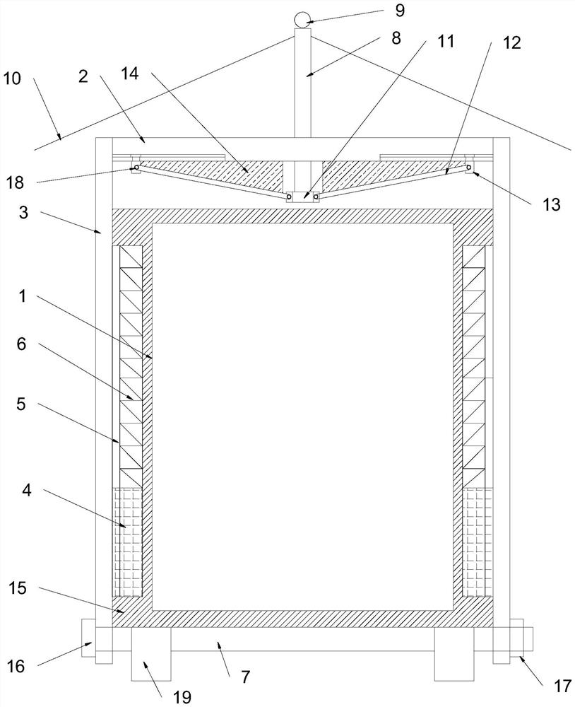
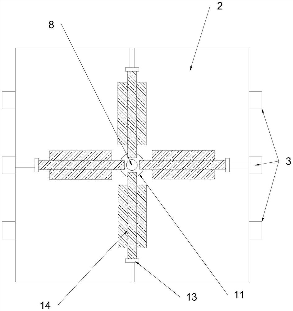
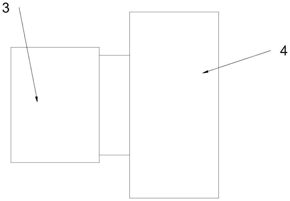
[0028] combine Figure 1 to Figure 3 The shown safety protection mechanism of a switchgear, in this embodiment, includes a supporting substrate 2 located above the switchgear body 1, and three pairs of supporting substrates are fixed on both sides of the supporting substrate 2 to abut on the side wall of the switchgear body 1. A set of longitudinal sliders 4 are fixed on the inner sides of the paired and oppositely arranged two groups of side bars 3 , and a longitudinal chute 5 slidingly connected with the longitudinal sliders 4 is provided on the side wall of the switchgear body 1 . The chute 5 is provided with a compression spring 6 for driving the longitudinal slider 4 upward; the bottom end of the side bar 3 is provided with a connecting hole, and a group of cross bars 7 are connected in the connecting holes of the two groups of side bars 3 arranged in pairs. The cross bar 7 spans and abuts against the bottom side of the switchgear body 1; a set of guide pillars 8 are pier...

Embodiment 2

[0036] see Figure 4 The switch cabinet safety protection mechanism shown in this embodiment differs from Embodiment 1 in that the top end of the longitudinal chute 5 runs through the raised reinforcement 15, and the bottom end of the compression spring 6 is fixed on the longitudinal chute. In the groove 5, its top pushes against the bottom side of the longitudinal slider 4, so it is only necessary to partially thicken the side wall of the switchgear body to set up the longitudinal chute, and it is not necessary to thicken all the side walls, which greatly saves material and reduce the weight of the cabinet.

Embodiment 3

[0038] see Figure 4The switch cabinet safety protection mechanism shown in this embodiment differs from Embodiment 1 in that an adjusting screw head 20 is provided on the top of the switch cabinet body 1, and the adjusting screw head 20 includes a threaded connection The screw in the switchgear body 1 and the adjustment plate connected to the top of the screw, the adjustment plate is used to abut against the bottom side of the connection plate 11, so when the switchgear is in a fixed state, the screw head can be adjusted by screwing , so as to limit it against the bottom side of the connection plate 11, so that it pushes the connection plate up until the buffer pad is pressed against the bottom side of the support base plate, so as to prevent the guide post and the shelter from shaking, and at the same time assist the compression spring Driving the jacking force can further strengthen the pressing force of the cross bar abutting against the bottom side of the cabinet, thereby...


PUM


Abstract

The invention provides a switch cabinet safety protection mechanism and a switch cabinet, the switch cabinet safety protection mechanism comprises a back shore substrate, two sides of the back shore substrate are fixedly provided with at least one pair of side rods abutting against the side wall of a switch cabinet body, the inner sides of the side rods are fixedly provided with longitudinal slide blocks slidably connected in the switch cabinet body, and the longitudinal slide grooves are internally provided with compression springs; connecting holes are formed in the bottom ends of the side rods, a group of cross rods are connected in the two groups of side rod connecting holes in a penetrating manner, and the cross rods stretch across and abut against the bottom side of the switch cabinet body; a group of guide columns penetrate through the center of the back shore base plate, a group of hanging rings are fixed at the top ends of the guide columns, a shielding shed used for shielding the upper portion of the switch cabinet body is fixed on the outer side of the guide columns, a connecting disc is fixed at the bottom ends of the guide columns, a plurality of groups of connecting rods are evenly hinged to the periphery of the connecting disc, and a group of sliding blocks are hinged to the ends of each group of connecting rods; the device is simple in structure, has a detachable mounting effect, is convenient to disassemble, assemble and maintain, can adapt to suspension transportation, and ensures higher transportation stability and safety.

Description

technical field [0001] The invention relates to a switch cabinet, in particular to a switch cabinet safety protection mechanism and a switch cabinet. Background technique [0002] The main function of the switchgear is to open and close, control and protect electrical equipment during the process of power generation, transmission, distribution and power conversion in the power system. The components in the switchgear mainly include circuit breakers, isolating switches, load switches, Composed of operating mechanism, transformer and various protection devices, there are many classification methods of switch cabinets. For example, according to the installation method of circuit breaker, it can be divided into removable switch cabinet and fixed switch cabinet; or according to the different cabinet structure, it can be divided into It is an open switchgear, metal-enclosed switchgear, and metal-enclosed armored switchgear; according to different voltage levels, it can be divided ...

Claims


Application Information

Patent Timeline
Patent Type & Authority Applications(China)
IPC IPC(8): H02B1/30H02B1/54H02B1/56
CPCH02B1/308H02B1/54H02B1/565
Inventor 宦俊葛敏朱文郭凡钱景季俊呈郭宇蒋杰朱军翟一骏戴红兵匡成祥于鑫童福根季辉张菲陈飞龙陈涛高成伟
Owner 江苏宏强电气集团有限公司
Why Eureka
Try Eureka