Vamp periphery pressing device for manual cloth shoe processing

A pressing device and technology for cloth shoes, applied to insoles, shoe uppers, footwear, etc., can solve problems such as messy countertops and inconvenient mold replacement, achieve clean worktables, improve replacement efficiency, and shorten the time for mold replacement

Inactive Publication Date: 2022-05-20
安徽纳工坊文化创新发展有限公司
View PDF0 Cites 0 Cited by
  • Summary
  • Abstract
  • Description
  • Claims
  • Application Information

AI Technical Summary

Problems solved by technology

[0003] The purpose of the present invention is to solve the problem of inconvenient mold replacement and messy tabletops in the prior art, and proposes a peripheral pressing device for shoe uppers for manual cloth shoe processing

Method used


Image

  • Vamp periphery pressing device for manual cloth shoe processing
  • Vamp periphery pressing device for manual cloth shoe processing
  • Vamp periphery pressing device for manual cloth shoe processing

Examples


Embodiment 1

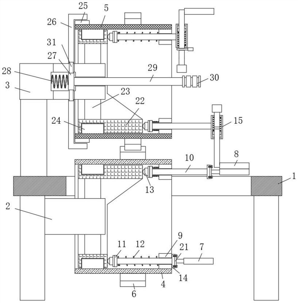
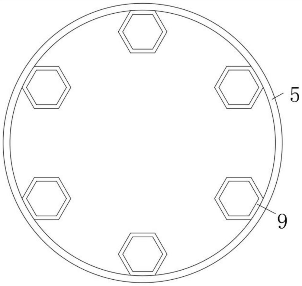
[0028] refer to Figure 1-4 , a pressing device around the vamp for manual cloth shoe processing, including an operating table 1, the table body of the operating table 1 is provided with a vertical through hole, and the bottom and top of the operating table 1 are fixedly connected with a lower horizontal shaft 2 and an upper horizontal shaft respectively. The shaft 3, the outer side of one end of the lower horizontal shaft 2 and the upper horizontal shaft 3 are respectively rotated to be provided with a lower mold storage cylinder 4 and an upper mold horizontal cylinder 5, the top of the lower mold storage cylinder 4 passes through the vertical through hole, and the lower mold storage cylinder 4 passes through the vertical through hole. The outer walls of the cylinder 4 and the upper mold horizontal cylinder 5 are coaxially fixedly connected with a synchronous gear ring 6 and meshed with each other. The lower mold storage cylinder 4 is provided with several bottom molds 7 that ...

Embodiment 2

[0032] Such as Figure 1-4As shown, this embodiment is basically the same as Embodiment 1. Preferably, the safety structure includes a safety gear ring 25 fixedly sleeved on the outside of one end of the upper mold horizontal cylinder 5, and a safety gear cover is provided on the outer meshing sleeve of one end of the safety gear ring 25. 26. The upper horizontal shaft 3 is provided with an inner cavity, and the inner wall of the inner cavity is divergently provided with several side holes. The inner sliding core 27 is slidably connected to the inner cavity, and the inner sliding core 27 is fixedly connected to the linkage shaft 31 on the peripheral side. One end of the linkage shaft 31 passes through the side hole and is fixedly connected with the inner wall of the safety tooth cover 26. A perforation is opened at the inner side of the inner cavity close to the upper mold horizontal cylinder 5, and one side of the inner sliding core 27 is fixedly connected with an outer extens...

Embodiment 3

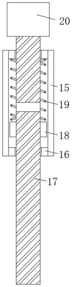
[0035] Such as Figure 1-4 As shown, this embodiment is basically the same as Embodiment 1. Preferably, the elastic downward pressure mechanism includes a vertical tube 15 fixed and rotated at one end of the polygonal sliding rod 10, and the inner wall of the opening at both ends of the vertical tube 15 is fixedly connected with a sealing ring 16. A lower pressing rod 17 runs through the vertical cylinder 15, and the outside of the rod body of the lower pressing rod 17 is fixedly provided with a ring stopper 18, which is slidably connected in the vertical cylinder 15, and the pressing die 8 is horizontally detachable and fixedly mounted on the end of the lower pressing rod 17 On one side of the head, the other end of the lower pressure rod 17 is fixedly connected with a handle one 20, and a spring two 19 is arranged between the side of the ring stopper 18 near the handle one 20 and the sealing ring 16.

[0036] In this embodiment, after completing the replacement, during subse...


PUM


Abstract

The vamp periphery pressing device for manual cloth shoe processing comprises an operation table, a vertical through hole is formed in a table body of the operation table, a lower transverse shaft and an upper transverse shaft are fixedly connected to the bottom and the top of the operation table correspondingly, and a lower mold storage cylinder and an upper mold transverse cylinder are rotationally arranged on the outer side of one end of the lower transverse shaft and the outer side of one end of the upper transverse shaft correspondingly; the outer wall of the lower die storage cylinder and the outer wall of the upper die transverse cylinder are coaxially and fixedly connected with synchronous gear rings and meshed with each other, a plurality of bottom dies capable of extending out of the top are arranged in the lower die storage cylinder, and a plurality of pressing dies capable of extending out of the bottom and matched with the bottom dies are arranged in the upper die transverse cylinder. According to the device, people can rapidly and synchronously replace the pressing die, the die is convenient and stable to use after being replaced, a working table is neater, the machining efficiency is improved, use of people is facilitated, and the use requirements of people in production and life are met.

Description

technical field [0001] The invention relates to the technical field of cloth shoe processing equipment, in particular to a peripheral pressing device for shoe uppers for manual cloth shoe processing. Background technique [0002] During the processing of cloth shoes, no matter in the process of bottom cutting, mesh bottom and flat bottom, it is necessary to use the upper and lower templates for pressing around. However, in the actual production process, the upper and lower templates used are different due to different shoe sizes. Different molds need to be used in different processes, so the types of molds need to be replaced frequently. When processing handmade cloth shoes at independent stations, it is necessary to prepare multiple sets of mold plates for replacement. The replacement process is very inconvenient, and When the mold is replaced, it is necessary to re-position and calibrate the mold, which takes a long time. Multiple spare molds also make the work surface ext...

Claims


Application Information

Patent Timeline
Patent Type & Authority Applications(China)
IPC IPC(8): A43D11/00
CPCA43D11/00
Inventor 李维斌
Owner 安徽纳工坊文化创新发展有限公司
Why Eureka
Try Eureka